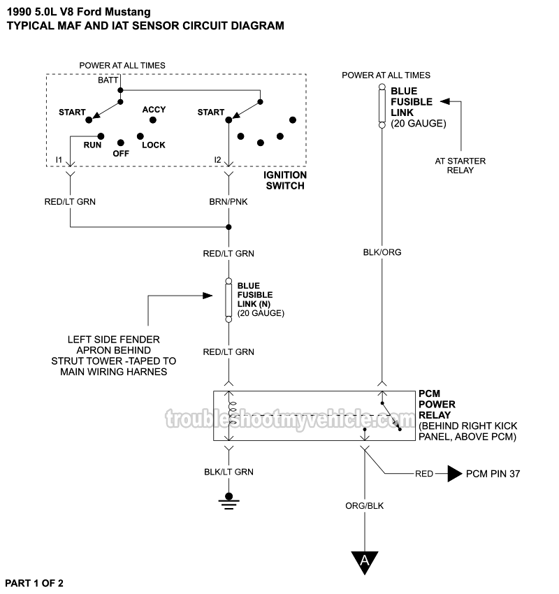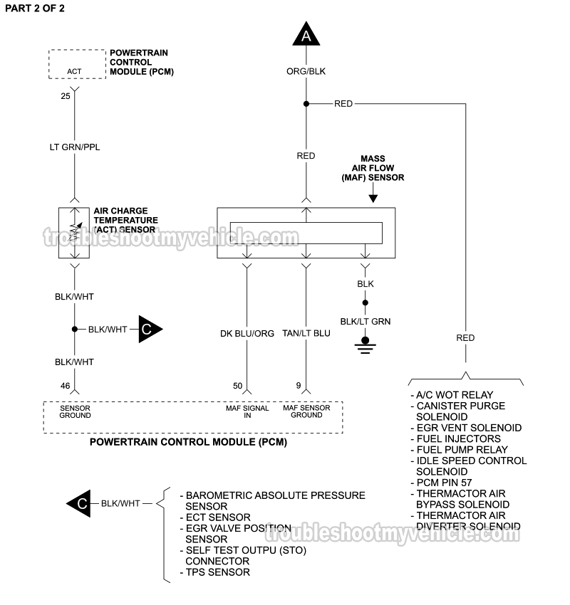

APPLIES TO: This mass air flow (MAF) and air charge temperature (ACT) sensor circuit wiring diagram applies to the following vehicles:
- 5.0L V8 Ford Mustang: 1990.
NOTE: This wiring diagrams includes the following component circuits:
- Mass Air Flow (MAF) Sensor.
- Air Charge Temperature (ACT) Sensor.
- EEC Power Relay (PCM Power Relay).
MAF SENSOR TESTS: The following tutorial will help you test the MAF sensor with a multimeter:
MAF Sensor Circuit Wiring Diagrams
- MAF Sensor And ACT Sensor Circuit Wiring Diagram (1991-1992 5.0L V8 Ford Mustang).
- MAF Sensor And IAT Sensor Circuit Wiring Diagram (1993 5.0L V8 Ford Mustang).
More 5.0L V8 Ford Mustang Diagnostic Tutorials
You can find a complete list of wiring diagrams and diagnostic tutorials for the 5.0L V8 Ford Mustang in this index:
Here's a sample of the diagnostic tutorials you'll find in the index:
- How To Test The Fuel Pump (1990-1995 5.0L V8 Ford Mustang).
- How To Test The Throttle Position Sensor (1994-1995 5.0L Ford Mustang).
- How To Test For A Blown Head Gasket (1990-1995 5.0L V8 Ford Mustang).
- How To Do And Interpret An Engine Compression Test (1990-1995 5.0L V8 Ford Mustang).

If this info saved the day, buy me a beer!

