Circuit Descriptions Of The 24X Crank Sensor
In the section you're going to find a brief description of the function of each wire coming out of the 24X crankshaft position sensor.
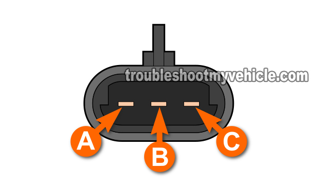
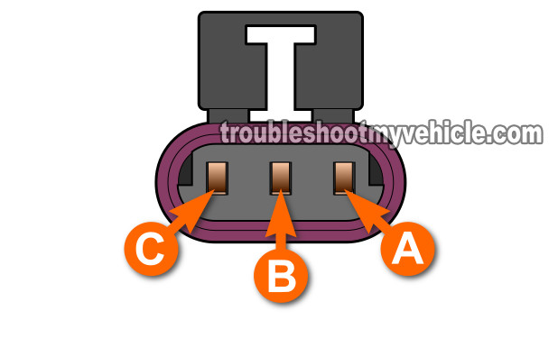
The connector on the sensor itself has male spade terminals (see illustration 1 of 2). The cranks sensor connector on the engine wiring harness has a female terminals (see illustration 2 of 2).
Circuit A:
- This wire feeds the 24X crank sensor with 12 Volts.
- These 12 volt are only available when the key is in the on position or when the engine is running.
Circuit B:
- This wire is a one that transmits the 24X crank signal to the fuel injection computer.
Circuit C:
- This wire feeds the sensor with Ground.
- This Ground is provided directly by the fuel injection computer. Be careful not to short this wire to 12 Volts or you will fry the computer.
Well, let's turn the page and start with the first crank sensor test.
The GM 3.1L & 3.4L 24X CKP Sensor Test
The 24X CKP sensor is located behind the front crankshaft pulley on all 3.1L and 3.4L engines that are equipped with this sensor. The connector of the 24X CKP sensor is located besides or above the air conditioning compressor.
As I mentioned at the beginning of the article, the 24X crank sensor test is a dynamic test done while the 24X sensor is still on the car or mini-van and in action (as it produces a 24X crank signal). You'll need to jack up the car, and so it goes without saying (but I'm gonna' say it anyway): Be careful, think safety all of the time, take all precautions, and use a jack stand to hold the car up in the air. Do not trust the jack!
- 1
Jack up the front passenger side of you car or mini-van and place a jack stand underneath to lower the vehicle onto.
- 2
Remove the front passenger-side wheel. If the wheel spins as you're trying to break the lug nuts loose, have someone sit inside the vehicle and step on the brake pedal. This will keep the wheel from moving and facilitate the removal of the lug nuts.
- 3
Remove the plastic water splash shield that protects the crankshaft pulley and serpentine belt from water.
- 4
Find the 24X CKP sensor's connector. This connector is usually on top of or beside the A.C. compressor. It may be necessary to remove some of the plastic wire loom protector that shields the three wires of the 24X CKP sensor.
- 5
Place the multimeter in Volts DC mode and with a wire-piercing probe or an appropriate tool, pierce the GREEN colored wire of the three wire connector. Connect the red multimeter test lead to this tool. The GREEN wire is the signal wire that transmits the 24X CKP sensor signal to the PCM.
To see what a what wire piercing probe tool looks like, click here: Wire Piercing Probe. - 6
Connect the black multimeter test lead to a good Ground point on the engine.
- 7
When everything is set up, turn the crankshaft pulley by hand in a clock-wise direction while you keep you eyes on the multimeter. Do not use the starter motor to crank the engine.
- 8
If the 24X sensor is working correctly, the multimeter will register an ON/OFF voltage of 9.5 to 10 Volts DC. ON is when the multimeter displays 9.5 to 10 Volts DC and OFF is 0 Volts DC. The key to see this voltage change is to turn the crankshaft pulley slowly and steadily.
Interpreting The Results Of The GM 24X CKP Sensor Test
Alright, you've done the above 24X CKP sensor test, now it's time to interpret the results your multimeter registered. Choose from the CASES below that best match your specific results:
CASE 1: The multimeter registered the ON/OFF 9.5 to 10 Volts DC as the crankshaft pulley was hand-turned. This result indicates that the 24X CKP sensor is creating a good 24X CKP signal and is working fine.
CASE 2: The multimeter DID NOT register the ON/OFF 9.5 to 10 Volts DC as the crankshaft pulley was hand-turned. This result indicates that the 24X CKP sensor is not creating a good 24X CKP signal.
Before replacing the 24X CKP sensor, you need to verify that it's getting power (12 Volts).
The wire that feeds the 24X crank sensor with power is the red one (of the 24X crank sensor connector). So the next step is to check that the RED wire has 12 Volts.
If this red wire does have 12 Volts, this tells you that the 24X crank sensor is getting power and the reason it IS NOT producing a crank signal is because the sensor is bad. Replace the sensor.
Related Test Articles
There are more 3.1L and 3.4L specific articles that I've written that may be of interest to you and you can find them all in this index:
Here's a sample of the tutorials you'll find in the index:
- How To Test The Camshaft Position Sensor (P0341) (GM 3.1L, 3.4L).
- How To Test The Blower Motor (GM 3.1L, 3.4L).
- How To Test The MAP sensor with a multimeter (GM 2.8L 3.1L, 3.4L).
- How To Troubleshoot A No Start (GM 3.1L, 3.4L).
- Testing The Ignition Module And Crank Sensor (7X Crank Sensor) (GM 3.1L, 3.4L) (at: easyautodiagnostics.com).

If this info saved the day, buy me a beer!


