TEST 1: Making Sure The O2 Heater Is Getting Power

The very first thing that we need to do, is to make sure that the front O2 sensor is getting power.
This power is in the form of 10 to 12 Volts DC and are present only with the key in the ON or RUN position.
In case you're wondering where this juice comes from, it comes from the O2 sensor fuse in the engine compartment fuse box (although you may need to consult your owner's manual in case you can't find it).
OK, to get our P0135 troubleshooting under way, this is what you need to do:
- Jack up the vehicle and support it on jack stands (if applicable).
- Never trust the jack to hold up the vehicle. Use jack stands!
- Disconnect the Bank 1 Sensor 1 Oxygen Sensor.
- If your vehicle has the 3.5L 5 cylinder engine, you only have 2 oxygen sensors, one before the catalytic converter and one after it. The one that you need to test is the one before the catalytic converter.
- If your vehicle has a V6 or a V8, you're looking at 3 to 4 oxygen sensors.
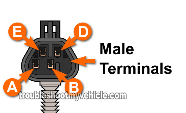
- Locate the D circuit wire of the engine wiring harness oxygen sensor connector.
- The letter D will be embossed on the connector.
- With the Key On Engine Off (KOEO), this wire should have 10 to 12 Volts DC.
Let's take a look at your test results:
CASE 1: 10 to 12 Volts are present in the D circuit wire. This tells you that you that the heater element within the oxygen sensor is getting power.
The next step is to make sure that the PCM is Grounding circuit E. For this test, go to: TEST 2: Making Sure The O2 Heater Is Getting Ground.
CASE 2: 10 to 12 Volts ARE NOT present in the D circuit wire. This usually means that the O2 sensor fuse, in the engine compartment fuse box is blown.
Check the fuse and if blown, replace it and retest.
NOTE: Usually, when the fuse is blown, you'll also see a P0141 DTC too, since this fuse also feed the Bank 1 Sensor 2 oxygen sensor with power.
TEST 2: Making Sure The O2 Heater Is Getting Ground

So far, you've reached this point because you have confirmed that the O2 sensor heater element is getting power (on the circuit D wire).
What we need to do next is to make sure that the PCM (Powertrain Control Module = fuel injection Computer) is activating the oxygen sensor's heater by applying a Ground on the circuit E wire.
IMPORTANT: Since the PCM is the one that provides this Ground, be careful and don't intentionally or accidentally short this wire to 12 Volts, or you'll fry the PCM.
This is what you'll need to do:
- Disconnect the rear oxygen sensor (if it isn't already from TEST 2).
- Locate the circuit E wire.
- You'll test the wire that is on the engine wiring harness oxygen sensor connector side.
- Place your multimeter in Volts DC mode and:
- Connect the red multimeter test lead to battery (+).
- Connect the black lead to the black w/ white stripe wire (BLK/WHT) of the engine wiring harness O2 sensor connector.
- With the Key On Engine Off (KOEO), this wire should have 10 to 12 Volts DC.
Let's take a look at your test results:
CASE 1: The multimeter registered the indicated voltage. This tells you that you that the PCM is providing a Ground and therefore is activating the heater element within the Oxygen Sensor for Bank 1 Sensor 1.
The next step is to check the resistance of the oxygen sensor's heater element itself. This resistance test will let you know if the heater element (inside the O2 Sensor for Bank 1 Sensor 1) is fried or not. For this test, go to: TEST 3: Testing The Heater Element's Resistance.
CASE 2: The multimeter DID NOT register the indicated voltage. This tells you that the PCM is bad (although this is extremely rare) or the wiring between the O2 sensor and the PCM has an open-circuit problem.
Although it's beyond the scope of this article, the next step for you is to:
- Check for continuity (with your multimeter) of the circuit E between the O2 sensor connector and the PCM.
TEST 3: Testing The Heater Element's Resistance

OK, having reached this point, we now know that the Bank 1 Sensor 1 oxygen (O2) sensor is getting power and Ground.
The next step (and the last one) is to check to see if the oxygen sensor's heater element is fried inside the O2 sensor itself.
This is a pretty easy test that you can do with your multimeter in Ohms mode and with the O2 sensor still installed on the exhaust manifold or exhaust pipe.
OK, this is what you need to do:
- Disconnect the oxygen sensor from the engine wiring harness connector (if it isn't already from the previous tests).
- Locate the O2 sensor wires that correspond to:
- The circuit D.
- -AND-
- The circuit E.
- Both of these letters should be embossed on the O2 sensor's connector to aid you in further identifying the circuits you need to test.
- With your multimeter in Ohms mode, check the resistance of this circuit.
- NOTE: Remember, you're testing the oxygen sensor itself.
- If all is OK, you should see about 4.5 Ω (Ohms).
- If the heater element is fried, your multimeter will show an open (usually indicated by the letters OL).
Let's take a look at your test results:
CASE 1: Your multimeter showed the indicated resistance. This tells you that you that the heater element within the oxygen sensor is OK.
CASE 2: Your multimeter showed an open circuit (OL). This confirms that the heater element inside the O2 sensor is bad. Replace the Bank 1 Sensor 1 oxygen sensor with a new one.
More 3.5L GM Tutorials
If you enjoyed and/or found this ‘How to’ article helpful, I have written several more 3.5L specific test articles. You can find a complete list of 3.5L tutorials here: GM 3.5L Index Of Articles.
- How To Test For A Blown Head Gasket (GM 3.5L, 4.2L).
- How To Diagnose A P0141 Heater Performance Bank 1 Sensor 2.
- How To Test The Intake Air Temp (IAT) Sensor (GM 3.5L).
- Ignition Coil-On-Plug (COP) Test (GM 3.5L, 4.2L).
- How To Test The Mass Air Flow (MAF) Sensor (GM 3.5L).
- How To Bench Test A Starter Motor (Step By Step) (at: easyautodiagnostics.com).

If this info saved the day, buy me a beer!


