
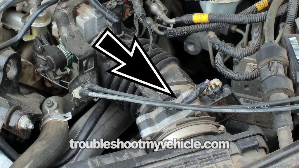
The mass airflow (MAF) sensor on the 1997-2001 3.1L V6 Buick Century can easily be tested without a scan tool. All you need is a multimeter that can measure Hertz frequency (If you don't have one, I'll show you where you can buy one without spending a fortune).
In this tutorial, I'm going to walk you through the three tests you need to find out if the MAF sensor is working correctly or if it's toast. We'll check that it's producing a MAF signal the PCM can use, and we'll also make sure it's receiving both power and Ground.
All of the test steps are explained in a step-by-step manner so that you can quickly figure out if the MAF sensor needs to be replaced or if the problem is somewhere else.
Contents of this tutorial:
- Common Symptoms Of A Bad MAF Sensor.
- Circuit Descriptions Of The MAF Sensor Connector.
- Where To Buy The MAF Sensor And Save.
- How Does The MAF Sensor Work?
- TEST 1: Testing The MAF Signal With A Multimeter.
- TEST 2: Making Sure The MAF Sensor Is Getting 12 Volts.
- TEST 3: Making Sure The MAF Sensor Is Getting Ground.
- More 3.1L V6 Buick Century Diagnostic Tutorials.
APPLIES TO: This tutorial applies to the following vehicles:
- 3.1L V6 Buick Century: 1997, 1998, 1999, 2000, 2001, 2002, 2003, 2004, 2005.
MAF SENSOR TESTS 1994-1996:
- How To Test The MAF Sensor (1994-1995 3.1L V6 Buick Century).
- How To Test The MAF Sensor (1996 3.1L V6 Buick Century).
Common Symptoms Of A Bad MAF Sensor
In a nutshell, the MAF sensor's job is to measure how much air is entering the engine, whether it's idling, cruising down the highway, or you're stepping on the gas.
The PCM uses this information to calculate the correct amount of fuel to inject into the engine under every driving condition.
Eventually, it's gonna fail and when it does, you're definitely going to notice one or more of the following engine performance problems:
- Check engine light ON: The check engine light is illuminated on the instrument cluster.
- MAF sensor trouble code: The PCM has stored a MAF sensor diagnostic trouble code in its memory.
- Lack of power: The engine feels sluggish or hesitates when you accelerate.
- Black smoke from the tailpipe: The engine is running excessively rich and producing black exhaust smoke.
- Poor fuel economy: Your Buick is using noticeably more fuel than normal.
- Rough idle: The engine idles rough or feels like it's about to stall.
- Starts then stalls: The engine starts but dies almost immediately afterward.
- Hard starting: The engine takes longer than normal to start.
MAF SENSOR CLEANING: If all your MAF sensor needs is a good cleaning, I've got a step-by-step tutorial that'll show you how to do it. Take a look at: How To Clean The GM Mass Air Flow (MAF) Sensor (at: easyautodiagnostics.com).
Circuit Descriptions Of The MAF Sensor Connector
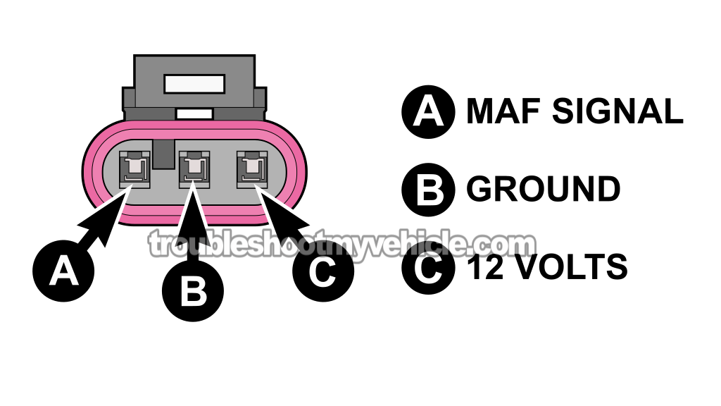
The MAF sensor on your Buick Century uses a 3-wire connector. Each wire (or circuit) is identified by the letter A, B, or C.
One circuit carries the MAF sensor's signal to the PCM, another supplies it with power, and the remaining circuit provides Ground.
In the table below, you'll find a brief description of what each circuit does. We're going to use this information in the diagnostic tests I've laid out in this tutorial.
| Terminal | Wire Color | Circuit Function |
|---|---|---|
| A | Yellow (YEL) | MAF Signal Output To PCM |
| B | Black with white stripe (BLK/WHT) | Chassis Ground |
| C | Pink (PNK) | 12 Volts From The ENG EMIS (10A) Fuse |
IMPORTANT: All of the tests in this tutorial are ON-CAR TESTS. Do not remove the MAF sensor from the vehicle or disconnect it from its air duct/plumbing.
Where To Buy The MAF Sensor And Save
The following links will help you to comparison shop for a known automotive name-brand MAF sensor (no knock-offs) for your 3.1L V6 Buick Century:


Disclosure: As an Amazon Associate, I earn from qualifying purchases. If my tutorials help you, using these links is an easy way to support the site at no extra cost to you. Thank you!
How Does The MAF Sensor Work?
To wrap our heads around the test we're about to perform, let's take a look at how the MAF sensor works in a very non-technical way:
- Inside the MAF sensor are two heated sensing wires. As air flows across them, it cools them off. The greater the amount of air entering the engine, the greater the cooling effect.
- The MAF sensor uses this cooling effect to generate a digital frequency signal that's measured in Hertz (Hz) and sends it to the PCM.
- As more air enters the engine (like when you accelerate it), the MAF sensor's Hertz value should increase.
- As less air enters the engine (like when it returns to idle), the Hertz reading should decrease.
The nice thing is that you don't need an expensive scan tool to test this signal. If your multimeter can measure Hertz frequency, you've got everything you need to find out if the MAF sensor is working correctly or if it's toast.
The most common failure of the MAF sensor (confirming that it's toast) is that the frequency reading stays stuck at one value regardless of engine speed or how far you open the throttle.
TEST 1: Testing The MAF Signal With A Multimeter
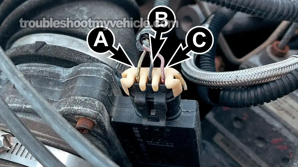
We're going to start our MAF sensor diagnostic by checking its output signal with a multimeter while the engine is running. We'll do this by connecting our multimeter to the MAF signal wire and watching how the Hertz (Hz) reading changes as we accelerate and let off the throttle.
Keep the following in mind:
- As engine speed increases, the Hertz reading should increase too.
- As engine speed returns to idle, the Hertz reading should decrease.
As I mentioned earlier, the most common failure of the MAF sensor is that its signal output stays stuck at one value regardless of engine speed (airflow).
If you don't have a multimeter that can measure Hertz (Hz) or you're looking to upgrade yours, this is the one I recommend: Tekpower TP8268 AC/DC Auto/Manual Range Digital Multimeter (Amazon affiliate link).
IMPORTANT: The MAF sensor must remain connected to its 3-wire connector during this test. You'll need to use either a back probe on the connector or a wire-piercing probe on the wire. This is the tool that I use, which works as both a back probe and a wire-piercing probe: Goupchn 4mm Banana to Banana Plug Test Leads Kit (Amazon affiliate link).
CAUTION: The engine must be running while you're performing this test. Keep your hands, clothing, and test leads away from any moving engine parts, and always think safety first.
Follow these test steps:
- 1
Set your multimeter to read Hertz (Hz) frequency.
- 2
Connect the black multimeter lead to the battery negative (-) terminal.
- 3
Connect the red multimeter lead to terminal A of the MAF sensor's connector (YEL wire). You'll need to use either a back probe or a wire-piercing probe to access the circuit while leaving the MAF sensor connected.
- 4
Start the engine and let it idle. If possible, perform this test with the engine at normal operating temperature.
- 5
Observe the Hertz reading on your multimeter with the engine idling.
The reading may remain very steady or fluctuate slightly. Both conditions are normal. This will be your idle (base) reading. - 6
Manually open the throttle while watching the multimeter's display.
As engine speed increases, the Hertz reading should increase too. - 7
Release the throttle and let the engine return to idle.
As engine speed decreases, the Hertz reading should decrease and return to approximately the same idle reading you observed in step 5. - 8
Repeat this test several times.
Every time you accelerate and let off the throttle, the Hertz reading should increase and decrease smoothly as engine airflow changes.
Let's take a look at what your test results mean:
CASE 1: The Hertz (Hz) reading increased as engine speed increased and decreased as the engine returned to idle. This is the correct test result and tells us that the MAF sensor is responding to changes in engine airflow just like it should. In other words, it's working correctly.
CASE 2: The Hertz (Hz) reading stayed fixed at one value regardless of engine speed. This isn't the correct test result and is usually a strong indication that the MAF sensor is defective.
Before we condemn the MAF sensor and replace it, however, we need to make sure it's getting the power it needs to operate. The next thing we're going to do is verify that it's receiving 10 to 12 Volts. Go to: TEST 2: Making Sure The MAF Sensor Is Getting 12 Volts.
TEST 2: Making Sure The MAF Sensor Is Getting 12 Volts
If the MAF sensor didn't produce a Hertz (Hz) signal that increased and decreased with changes in engine speed, the next thing we need to do is make sure it's getting power.
Power is supplied to the MAF sensor through the pink (PNK) wire of the sensor's 3-wire connector. This wire connects to terminal C of the connector.
The power source for the PNK wire is the ECM (15A) fuse located in the dash fuse box.
We're going to verify that this power supply is present with a simple multimeter voltage test. If your multimeter registers 10 to 12 Volts, then we can rule out a power supply problem and move on to our last diagnostic test.
Let's get started:
- 1
Disconnect the MAF sensor from its electrical connector.
- 2
Set your multimeter to Volts DC mode.
- 3
Connect the black multimeter lead to the battery negative (-) terminal.
- 4
Turn the ignition key to the ON position, but don't crank or start the engine.
- 5
Touch the red multimeter lead to the front of terminal C (PNK wire) on the MAF sensor connector.
CAUTION: Probe the female terminal carefully to avoid damaging or spreading it. - 6
Your multimeter should register 10 to 12 Volts DC.
Let's take a look at what your test results mean:
CASE 1: Your multimeter registered 10 to 12 Volts. This is the correct test result and tells us that the MAF sensor is getting the power it needs to create a MAF signal.
For our final test, we'll make sure it's getting Ground. Head over to: TEST 3: Making Sure The MAF Sensor Is Getting Ground.
CASE 2: Your multimeter did NOT register 10 to 12 Volts. Without power, the MAF sensor won't be able to produce a MAF signal.
Your next step is to troubleshoot why these 10 to 12 Volts are missing. Your first stop is to pull the ENG EMIS (10A) fuse and check to see if it's blown. If the fuse isn't the issue, then you'll need to check the pink (PNK) wire for an open-circuit problem.
Once you've repaired the problem that's causing the missing power supply, the MAF sensor should begin functioning normally and the MAF sensor trouble code should clear itself (assuming there aren't any other problems).
TEST 3: Making Sure The MAF Sensor Is Getting Ground
The previous two tests have confirmed the following:
- TEST 1: The MAF sensor's signal is either missing or stuck at one value regardless of how much we open or close the throttle.
- TEST 2: The pink (PNK) wire that connects to terminal C is delivering 10 to 12 Volts to the MAF sensor.
For our final diagnostic test, we're going to make sure that terminal B of the sensor's 3-wire connector is delivering Ground. Terminal B corresponds to the black with white stripe (BLK/WHT) wire of the connector.
Keep in mind that this is a chassis Ground, so it's available at all times regardless of the ignition key's position.
We're going to check this circuit with a simple multimeter voltage test. If Ground is present, we'll have all the information we need to determine whether the MAF sensor itself is defective or if something else is causing the problem.
Follow these test steps:
- 1
Disconnect the MAF sensor from its electrical connector.
- 2
Set your multimeter to Volts DC mode.
- 3
Connect the red multimeter lead to the battery positive (+) terminal.
- 4
Touch the black multimeter lead to the front of terminal B (BLK/WHT wire) on the MAF sensor connector.
CAUTION: Probe the female terminal carefully to avoid damaging or spreading it. - 5
Your multimeter should register 10 to 12 Volts DC.
NOTE: Since this is a chassis Ground, this voltage should be present regardless of the ignition key's position.
Let's take a look at what your test results mean:
CASE 1: Your multimeter registered 10 to 12 Volts. This is the correct test result and tells us that the MAF sensor has a good Ground.
If all three of the following conditions are true, then you can conclude that the MAF sensor is defective and needs to be replaced:
- TEST 1: The MAF sensor's Hertz (Hz) signal was missing or stayed fixed at one value regardless of engine speed (airflow).
- TEST 2: The MAF sensor is getting power (10 to 12 Volts).
- This test section: The MAF sensor has a good Ground on its Ground circuit.
CASE 2: Your multimeter did NOT register 10 to 12 Volts. This test result tells us that the MAF sensor isn't receiving the Ground it needs to operate. Without it, the sensor won't be able to produce the signal the PCM needs to see.
Your next step is to troubleshoot why this wire isn't providing Ground to the MAF sensor. The most likely cause is an open-circuit problem in the wire itself or a corroded Ground connection where the wire attaches to the engine or chassis.
Once you've repaired the issue that's causing the missing Ground, the MAF sensor should begin functioning normally again, and the MAF sensor trouble code should clear itself (assuming there aren't any other problems).
More 3.1L V6 Buick Century Diagnostic Tutorials
You can find a complete list of 3.1L V6 Buick Century tutorials and wiring diagrams in this index:
Here's a small sample of the tutorials you'll find in the index:
- How To Test An Engine No-Start (1994-2005 3.1L V6 Buick Century).
- How To Troubleshoot A Cylinder Misfire (1994-2005 3.1L V6 Buick Century).
- How To Test The Fuel Injectors (1994-1999 3.1L V6 Buick Century).
- How To Test The Ignition Control Module (1994-2005 3.1L V6 Buick Century).

If this info saved the day, buy me a beer!
