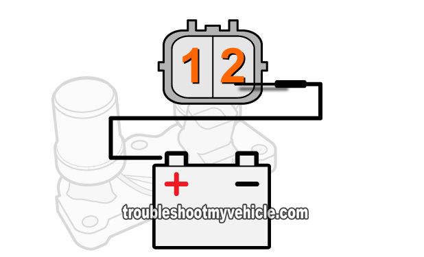
TEST 2: Applying 12 V To Solenoid A
After making sure that solenoid valve A's internal resistance is within 14 to 25 Ωs... the next step is to apply 12 Volts directly to it.
You're gonna' apply this voltage directly from your Honda Civic's battery.
IMPORTANT: Remember that the lock-up solenoid assembly gets Ground thru' its base, so if you perform this test with it removed from the transmission, you'll need to Ground the assembly to the battery negative (-) terminal using something like a jump-start cable.
These are the test steps:
- 1
Unplug the lock up solenoid assembly from its electrical connector.
NOTE: This test is done on the lock-up solenoid's connector AND NOT on the engine wiring harness' pigtail connector. - 2
Apply 12 Volts to terminal #2, of the lock-up solenoid assembly's connector, using a jumper wire or a power probe.
- 3
You should hear an audible click when the 12 Volts are applied.
Repeat this test as many times as you need to be certain of your test results.
CASE 1: Solenoid valve A clicked when you applied 12 Volts. This test result tells you that the solenoid is opening and closing.
CASE 2: Solenoid valve A DID NOT click when you applied 12 Volts. This test result tells you that shift solenoid A is bad and needs to be replaced.
Since shift solenoid A is part of the lock-up solenoid assembly, you'll need to replace the entire assembly to solve the issue.
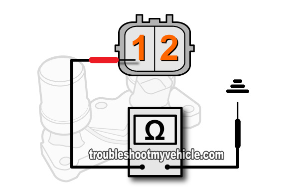
TEST 3: Solenoid B Resistance Test
Testing solenoid valve B, of your Honda Civic's lock-up solenoid assembly, involves 2 specific tests.
The first one, and the focus of this test section, is checking its internal resistance. The second test is applying battery voltage to it (and you'll do this in TEST 4).
Since the factory resistance specification is for the lock-up solenoid assembly at room temperature, you need to make sure that you Honda Civic's engine and transmission (and thus the lock-up solenoid assembly) is completely cold.
These are the test steps:
- 1
Place your multimeter in Ohms mode.
- 2
Unplug the lock up solenoid assembly from its electrical connector.
NOTE: This test is done on the lock-up solenoid's connector AND NOT on the engine wiring harness' pigtail connector. - 3
Measure the resistance between terminal labeled with the #1, in the image viewer above, and the solenoid assembly's body.
NOTE: The TCC lock-up solenoid is Grounded internally thru' the solenoid assembly's case. If the solenoid assembly is still bolted to the transmission housing, you can Ground your multimeter's lead directly on the battery's negative (-) terminal. - 4
The multimeter should register 14-25 Ohms for the resistance value of TCC lock-up solenoid.
Let's take a look at what your test results mean:
CASE 1: Solenoid valve B's resistance is between 14-25 Ohms. This is the correct and expected test result and generally means that the TCC lock-up solenoid is OK.
Although the TCC lock-up solenoid passed this test, there's still one more we need to do, which is to manually apply power to the solenoid and see if it clicks. Go to: TEST 4: Applying 12 V To Solenoid B.
CASE 2: Solenoid valve B's resistance WAS NOT between 14-25 Ohms. Recheck your multimeter test connections and retest. If you still don't get the correct resistance, then solenoid B, of the lock-up solenoid assembly, is bad.
Since solenoid valve B is part of the lock-up solenoid assembly, you'll need to replace the entire assembly to solve the issue.


