TEST 4: Checking Continuity Of The Ground Circuit
In this test step, we're gonna' check and confirm that the Ground circuit (wire) of the TPS has continuity.
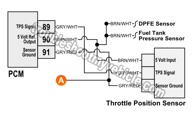
The PCM provides a Ground for the throttle position sensor thru' the GRY/RED (gray w/ red stripe) wire of the throttle position sensor connector.
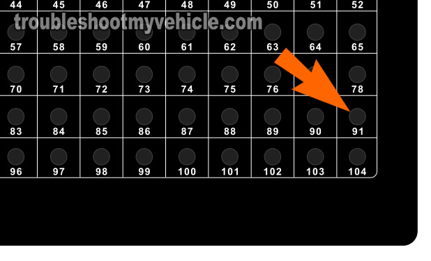
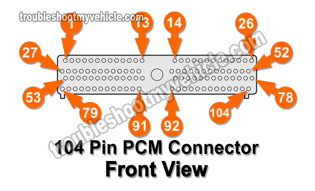
The other end of the GRY/RED wire connects to pin 91 of the PCM 104 pin connector.
IMPORTANT: Do not probe the front of the PCM 104 connector or you'll damage the terminal. This will require that you replace the entire engine wiring harness.
OK, these are the test steps:
- 1
Disconnect the battery negative cable and then unplug the PCM from its connector.
IMPORTANT: The battery negative cable will remain disconnected from the battery negative post for the remainder of the test. - 2
Connect the breakout box to the 104 pin PCM connector only. Do not connect the the Ford 104 pin breakout box to the PCM.
- 3
Place your multimeter in Ohms mode (Ω). We'll be checking the continuity of the circuit by checking its resistance.
- 4
Measure resistance between breakout box pin 91 and TPS connector terminal that connects to the GRY/RED wire.
The GRY/RED wire is the wire that connects to terminal 91 of the PCM 104 pin connector. - 5
Your multimeter should register 5 Ohms or less if the circuit is OK and has continuity.
Let's take a look at what your test results mean:
CASE 1: Your multimeter registered 5 Ohms or less. This test result tells you that the GRY/RED wire is not ‘open’ between the TPS connector and the PCM 104 pin connector.
Your next step is to check the power circuit of the TPS. For this test go to: TEST 5: Checking TP Signal Circuit For Short to Power or Ground.
CASE 2: Your multimeter DID NOT register 5 Ohms or less. If the resistance value is in the thousands of Ohm or your multimeter registered OL (over limit), then the GRY/RED wire is ‘open’.
Your next step is to repair the open in the GRY/RED wire and restore the Ground since, somewhere between the PCM connector and the TPS connector, this wire is broken.
TEST 5: Checking TP Signal Circuit For Short To Power Or Ground
If you've reached this point, you have confirmed that all 3 TPS circuits (wires) have continuity.
Now, we'll check that the throttle position sensor's signal circuit (the GRY/WHT wire) is not shorted to power .Specifically that the TP signal circuit is not shorted to VPWR or 5 V REF.
We'll also check that the TP signal circuit is not shorted to Ground. Specifically that the circuit is not shorted to PWR GND or Sensor Ground.
Checking for a ‘short to power’ or a ‘short to Ground’ involves another round of continuity tests and I'll show you which breakout box pins you'll need to check.
IMPORTANT: Do not probe the front of the PCM 104 connector or you'll damage the terminal. This will require that you replace the entire engine wiring harness.
OK, these are the test steps:
- 1
Disconnect the battery negative cable and then unplug the PCM from its connector.
IMPORTANT: The battery negative cable will remain disconnected from the battery negative post for the remainder of the test. This will render the power circuits without battery power and make possible the multimeter continuity tests. - 2
Connect the breakout box to the 104 pin PCM connector only. Do not connect the the Ford 104 pin breakout box to the PCM.
- 3
Place your multimeter in Ohms mode (Ω) to check for shorts to power by measuring resistance between:
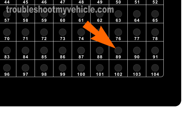
Breakout box pin 89 and breakout box pin 71.
Breakout box pin 89 and breakout box pin 90.
Breakout box pin 89 and breakout box pin 97.
NOTE 1: Continuity SHOULD NOT exist between any of the pins above.
NOTE 2: Pin 71 and Pin 97 are VPWR circuits that carry battery power derived from the PCM Power Relay. Pin 90 is the circuit that feeds the TPS with 5 Volts DC. - 4
Place your multimeter in Ohms mode (Ω) to check for shorts to Ground by measuring resistance between:
Breakout box pin 89 and breakout box pin 91.
Breakout box pin 89 and breakout box pin 24.
Breakout box pin 89 and breakout box pin 103.
NOTE 1: Continuity SHOULD NOT exist between any of the pins above.
NOTE 2: Pin 24 and Pin 103 are Ground circuits that connect to chassis Ground. Pin 91 is the circuit that feeds the TPS with Ground. - 5
Your multimeter SHOULD NOT register continuity between the pins tested in step 3 and step 4.
To be a bit more specific: Your multimeter SHOULD NOT register a resistance of 5 Ohms or less. The resistance value should be 10,000 Ohms or more (usually OL).
Let's take a look at what your test results mean:
CASE 1: Your multimeter DID NOT register continuity in the pin tests above. This is the correct and expected test result and tells you that the GRY/WHT wire of the TPS connector is not shorted to power or Ground.
If you have:
- Confirmed that the TPS is OK (because you either replaced it or have tested it).
- Confirmed the continuity TPS signal, power and Ground circuits (TEST 2, TEST 3, and TEST 4).
- Confirmed that the TPS signal circuit is not shorted to power or Ground (in this test section).
and yet the PCM is still accusing the TPS as being bad, you should take a look at this section: TPS Power And Ground Circuits Shorted to Power or Ground.
CASE 2: Your multimeter registered 5 Ohms or less in one of the pin tests above.
This test result tells you that the TP signal GRY/WHT wire is shorted to the specific circuit (wire) that registered continuity on your multimeter.
Your next step is to physically check the length of the engine wiring harness (between the TPS connector and PCM connector) for any obvious damage.
Repairing the short between these two circuits will solve the throttle position sensor problem lighting up the check engine light (CEL) on your Ford vehicle.


