TEST 1: Checking The Throttle Position Sensor (TPS) Signal

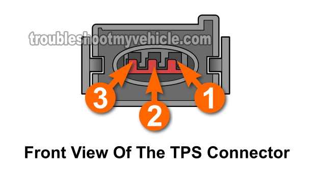
When the TP sensor is working correctly, the voltage it produces (and sends the PCM on circuit #2) increases and decreases depending on the amount the throttle plate opens.
So, the first thing we'll do is connect a multimeter to circuit #2 and manually open and close the throttle and see if the TP sensor voltage signal increases and decreases.
If the signal doesn't move (increase or decrease) or the voltage signal shows gaps, then the TP sensor is bad and needs to be replaced.
If you don't have a multimeter or need to upgrade yours? Check out my recommendation: Buying A Digital Multimeter For Automotive Diagnostic Testing (found at: easyautodiagnostics.com).
Here are the test steps:
- 1
Place your multimeter in Volts DC mode.
- 2
Turn the key on but don't crank or start the engine.
- 3
Connect the red multimeter test lead to circuit #2.
NOTE: The TP sensor connector needs to be connected to the TPS, so you'll need to either back-probe the connector or use a wire piercing probe to get to the signal inside the wire (to see what a wire piercing probe looks like: Wire Piercing Probe Tool). - 4
Ground the black multimeter test lead directly on the battery negative (-) post.
- 5
Manually rotate the throttle.
You'll get the best results by opening and closing the throttle directly on the throttle body instead of stepping on the accelerator pedal. - 6
The multimeter should show an increasing voltage as you (or your helper) open up the throttle.
You'll get the best results by opening and closing the throttle directly on the throttle body instead of stepping on the accelerator pedal. - 7
The multimeter should show a decreasing voltage as you begin to close the throttle.
- 8
Using a screwdriver's handle, gently tap the TP sensor as you open and close the throttle and observer the multimeter.
The purpose (of tapping the TP sensor with the screwdriver's handle) is to see if the TP sensor shows gap's in the voltage signal. Why? Because a good TP sensor will show a continuous increasing or decreasing voltage signal even while getting tapped by the screw-driver's handle.
Let's take a look at what your test results mean:
CASE 1: The TP sensor signal's voltage increased or decreased smoothly and without gaps. This test result tells you that the TPS is OK.
This test result also tells you that:
- Circuit #1 is providing Ground.
- Circuit #3 is providing power (5 Volts).
CASE 2: The TP sensor signal's voltage DID NOT increase or decrease smoothly and/or showed gaps. This test result usually tells you that the throttle position sensor (TPS) is fried and needs to be replaced but not always.
We need to do one more test to make sure and that's to verify that the TP sensor is getting both power and Ground. For this test, go to: Checking Throttle Position Sensor (TPS) Power And Ground.
TEST 2: Checking Throttle Position Sensor (TPS) Power And Ground

If the TP sensor doesn't get power or Ground (or both), it's not gonna' produce a TP sensor voltage signal.
So, if in TEST 1 the TP sensor did not produce a decreasing or increasing voltage signal, the next step is to make sure the sensor is being fed both power and Ground.
If this test shows that the TP sensor is getting both power and Ground, then we can confidently conclude that the TP sensor is bad and needs to be replaced.
With the multimeter if Volts DC mode, this is what you need to do:
- 1
Check circuit #1 for Ground with the Key On Engine Off (KOEO).
Connect your multimeter's black test lead to circuit #1 and the red lead to the battery positive (+) post.
The multimeter should register battery voltage (12+ Volts). - 2
Check circuit #3 for power with the Key On Engine Off (KOEO).
Connect your multimeter's red test lead to circuit #3 and the black lead to the battery negative (-) post.
The multimeter should register 4.5 to 5 Volts DC.
Let's analyze your TPS test result:
CASE 1: Both Ground and power (5 Volts) are present. This is the correct and expected test result.
Since you have now confirmed (in TEST 1) that the TP sensor is not producing a signal and in this test you've confirmed that the sensor is getting both power and Ground, you can conclude the TP sensor is bad and needs to be replaced.
CASE 2: Either Ground or power ARE NOT present. This test result exonerates the TP sensor as being bad and tells you that the reason the TP sensor is not producing an increasing/decreasing voltage signal in TEST 1 is because it's missing power or Ground.
Although it's beyond the scope of this tutorial, you'll need to find out why this signal is missing to get the TP sensor back on the job.

