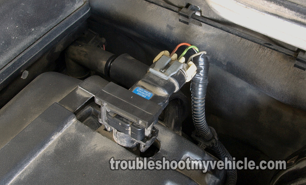
In this tutorial, I'm gonna' show you the fastest and surest way to test the manifold absolute pressure (MAP) sensor on your 3.5L or 4.2L equipped GM pickup or SUV. Not only that, the MAP sensor test I'm gonna' show you doesn't require a scan tool (to test the manifold absolute pressure (aka MAP) sensor).
Now, in case you're wondering how we're gonna' test the MAP sensor., I'll show you how to test it using a multimeter and a vacuum pump (and if you don't have a vacuum pump, you can just suck on the MAP sensor's nipple using a vacuum hose and the good ole' lungs).
This tutorial should also help you diagnose the following trouble codes: P0106, P0107, and P0108. Now, don't worry, this is a step-by-step test that will tell you whether you have a bad MAP sensor or not on your hands.
Contents of this tutorial:
- Symptoms Of A Bad MAP Sensor.
- What Tools Do I Need To Test The MAP Sensor?
- What Does The MAP Sensor Do?
- Where To Buy The MAP Sensor And Save.
- Circuit Descriptions Of The MAP Sensor.
- TEST 1: Checking The MAP Sensor Signal.
- TEST 2: Making Sure The MAP Sensor Is Getting 5 Volts.
- TEST 3: Making Sure The MAP Sensor Is Getting Ground.
![]() You can find this tutorial in Spanish here: Cómo Probar El Sensor MAP (3.5L V6 GM) (at: autotecnico-online.com).
You can find this tutorial in Spanish here: Cómo Probar El Sensor MAP (3.5L V6 GM) (at: autotecnico-online.com).
Symptoms Of A Bad MAP Sensor
The most obvious symptom, you'll see when the manifold absolute pressure (MAP) sensor fails, is the check engine light (CEL) shining nice and bright on your instrument cluster.
You'll also see one or several of the following symptoms:
- Diagnostic Trouble Codes:
- P0106: Manifold Absolute Pressure (MAP) System Performance.
- P0107: Manifold Absolute Pressure (MAP) Circuit Low Voltage.
- P0108: Manifold Absolute Pressure (MAP) Circuit High Voltage.
- Bad gas mileage.
- Won't pass the emissions test.
What Tools Do I Need To Test The MAP Sensor?
Here's a basic list of tools you'll need:
- A multimeter.
- You'll only be using the multimeter to check voltage DC and resistance (Ohms).
- If you need to upgrade or buy a multimeter, check out my recommendation: Buying A Digital Multimeter For Automotive Diagnostic Testing (found at: easyautodiagnostics.com).
- A vacuum pump.
- If you don't have one and/or need to buy one, this is the one that I recommend and you can buy it here: MV8000 Automotive Tune-up and Brake Bleeding Kit.
- Wire piercing probe.
- Although this tool is not an absolute must, if you do buy one, you'll realize just how easy it makes testing the voltages inside the wires.
- If you need to see what this tool looks like, you can see it here: Wire Piercing Probe.
- Scan tool.
- You don't need one to use the info in this tutorial but how else are you gonna' check for the MAP sensor codes?
- Don't have one? Check out my recommendation: Abe's Scan Tool Recommendation.
What Does The MAP Sensor Do?
The MAP sensor's job is to measure the vacuum pressure inside the intake manifold when the engine is running.
Vacuum is created within the intake manifold as the pistons travel downward and draw air on their intake stroke.
The PCM (Powertrain Control Module = Fuel Injection Computer) will use the MAP sensor input, along with the inputs of the MAF sensor and throttle position sensor (TPS) to calculate fuel injection and ignition timing (among several things).
The MAP sensor needs three very important things to work and these are:
- 5 Volts.
- A Ground.
- Vacuum.
The way that we're gonna' test the MAP sensor is independent of engine vacuum. We'll supply our own vacuum with a vacuum pump. Why? Because a few different engine conditions/malfunctions can fool the PCM into thinking that the MAP sensor is bad when it really isn't.
So the surest way to make sure that the MAP sensor is OK or not, is to verify its signal with a vacuum pump and I'll show you how to do that in this tutorial.
Where To Buy The MAP Sensor And Save
The following links will help you to comparison shop for the OE MAP sensor (avoid buying a knock-off with a weird brand name):
Not sure that the above MAP sensor fits your particular vehicle? Don't worry, once you get to the site they'll make sure it fits. If it doesn't, then they'll find you the right one.
Circuit Descriptions Of The MAP Sensor

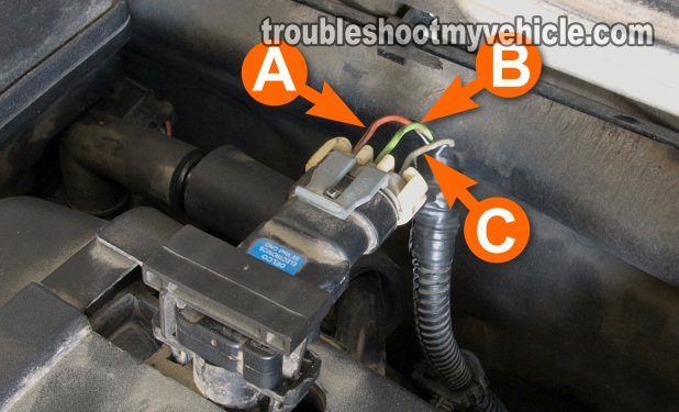
The MAP sensor has 3 wires coming out of its connector.
Each wire (circuit) is identified by a letter on the connector itself (if you take a close look at the connector, you'll see the letters A, B, and C embossed on it).
Each wire (circuit) has a specific job to do and below are those job descriptions.
IMPORTANT: The color of the wires below are probably not gonna be the ones on your particular vehicle and this is OK. Why? Because the circuit descriptions are all the same irrespective of the color of the wire.
| MAP Sensor Sensor Circuits | ||
|---|---|---|
| Pin | Wire Color | Description |
| A | Orange w/ Black stripe | Ground (known as: Low Reference) |
| B | Light Green | MAP Sensor Signal |
| C | Grey | 5 Volt Reference |


