How To Read The CMP Images

I tried to make this article as simple and as easy as possible to follow. The easiest place I have found, in my personal experience, is to test the cam sensor's signals at the ignition control module's connector.
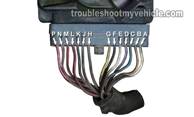
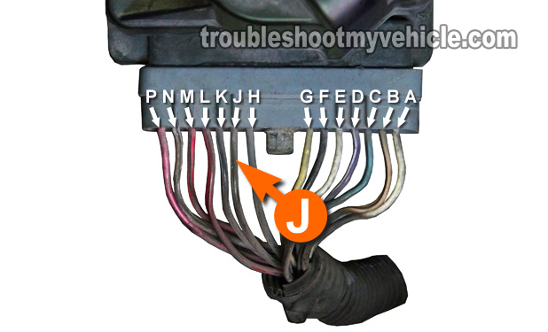
And so, the photos I'm using in this article are of the ignition control module's connector. The letters J, M, and N are the circuits (wires) that connect between the camshaft position sensor and the ignition control module and this is where you'll be doing the tests I've described here.
- On the connector, of the ignition control module (ICM), on your 3.8L GM equipped vehicle, you can see that GM has molded the letters M thru' A.
- GM, as most of the electronics industry, has omitted the letters i and o. This is normal and done intentionally.
- As your looking down at the ignition control module (and its connector) the letter P circuit starts on your left and the letters regress to the letter A from there.
- The cam sensor test in this article will deal only with the following circuits:
- Wire labeled with the letter J.
- Wire labeled with the letter N.
- Wire labeled with the letter M.
You can use a digital multimeter or an analog meter, although I suggest using a digital multimeter for it's accuracy.
OK, let's get testing.
CMP TEST 1: Cam Signal Test

The camshaft position sensor is located on the front timing cover, above the crankshaft pulley and next to the water pump pulley.
We're not going to test for the cam sensor signals at the cam sensor connector itself. Instead, you'll be testing for these signals at the ignition control module's connector. Also, this test requires that you manually crank the engine using a 1/2 inch ratchet and the appropriate socket and extension.
Since you'll test the sensor while the engine is being cranked (by hand, that is). You'll need to jack up the car or mini-van, and so it goes without saying (but I'm gonna' say it anyway): Be careful, think safety all of the time, take all precautions, and use a jack stand to hold the car up in the air. Do not trust the jack!
I also recommend that you read this entire article first, especially familiarize yourself with the working theory of the camshaft position sensor found in the subheading How The Cam (CMP) Sensor Works. OK, here's the test:
- 1
To make it easier to turn the crankshaft pulley (by hand), you'll need to raise the front of the car or mini-van and place it on jack stands.
- 2
Once the vehicle is up in the air, remove the front passenger-side wheel and the water splash shield (that protects the serpentine belt from water splash).
- 3
As an important safety precaution, disable the fuel system by disconnecting all 6 fuel injectors from their electrical connectors. This is important! By disabling all 6 fuel injectors, you'll keep the vehicle from possibly starting as you perform the test.
- 4
Locate the ignition control module's connector and disconnect it from the ignition control module (ICM). Once disconnected, remove enough of the plastic wire loom protector and black electrical tape that shields the wires of the ICM connector.
- 5
Once you have removed enough of this black electrical tape insulation, reconnect the connector to the ignition control module. All of the tests in this article are done with the ignition control module (ICM) connected to its electrical connector.
- 6
With a wire-piercing probe or an appropriate tool, pierce the wire labeled with the letter J in the photo above. Connect the red multimeter test lead to this tool. Turn your multimeter on and place it in Volts DC mode.
To see what a what wire piercing probe tool looks like, click here: Wire Piercing Probe.
This wire (circuit) is the one that brings the cam signal to the ignition control module (ICM). The cam sensor signal does not go directly to the fuel injection computer. - 7
Connect the black multimeter test lead to a good Ground point on the engine, preferably on the battery negative (-) terminal.
- 8
Using a 1/2 inch ratchet, an extension and the appropriate socket, turn the crank pulley by hand in a clock-wise direction while you observe your multimeter's display. Do not use the starter motor to crank the engine, since this test will not work if you use the starter motor.
- 9
What you're looking for, as you manually turn the engine, is for the multimeter to display one and only one voltage value of 0 Volts per 2 complete revolution of the crankshaft pulley.
Let me explain this a bit further, most of the time that you'll be turning the crank pulley, your multimeter will register between 5 to 7 Volts DC. Now, when the interrupter on the cam gear activates the cam sensor, the reading on your multimeter will drop down to 0 Volts. This will be a momentary drop, because as soon as the interrupter magnet passes the CMP sensor, the voltage will go back up to 5 to 7 Volts DC.
In case you're wondering why you have to turn the crank pulley so much for only one cam sensor signal output, it's because the camshaft turns only one complete revolution for every 2 complete turns of the crankshaft.
CASE 1: The multimeter registered the 0 Volts DC once, as you hand-cranked the engine two full revolutions. This result confirms that the camshaft position sensor is working. This test has eliminated the camshaft position sensor as bad.
No further testing is required, since this test proves that the CMP sensor is creating the appropriate signal.
CASE 2: The multimeter DID NOT register the 0 Volts DC once, as you hand-cranked the engine two full revolutions. This usually indicates that the camshaft position sensor is bad, but it's best to perform three more tests to be absolutely sure.
The first test is to see if the camshaft position sensor is missing power and/or Ground (since without these two, it won't produce a cam signal). We'll be checking for these two items in CMP TESTS 2 and 3.
If power and Ground are present, then the next step is to visually check that the CAM magnet button (technically called: camshaft position sensor interrupter) hasn't fallen off the camshaft gear. If the CMP interrupter has fallen off, the cam sensor won't produce a cam signal.
Don't worry, this tutorial takes all of these possibilities into consideration and we'll be testing them all. For now, your next step is to go to: CMP TEST 2: Power Circuit.
