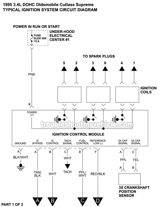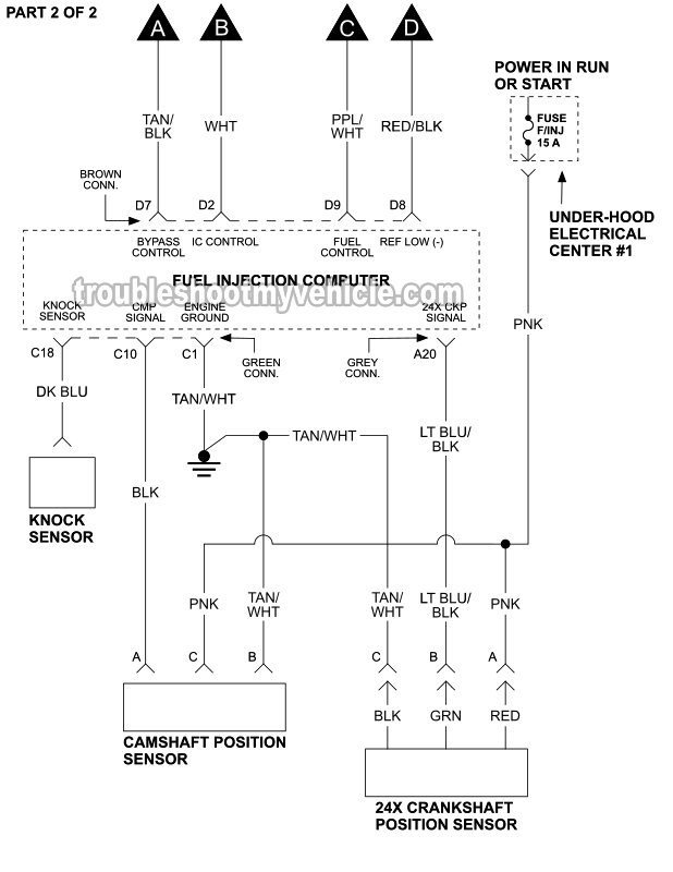

APPLIES TO: This simplified ignition system wiring diagram applies to the following vehicles:
- 1995 3.4L DOHC V6 Oldsmobile Cutlass Supreme.
This circuit diagram includes the following circuits:
- Ignition coil packs.
- 3X Crankshaft position (CKP) sensor.
- Also known as the Low Resolution Crankshaft Position Sensor.
- 24X Crankshaft position (CKP) sensor.
- Also known as the High Resolution Crankshaft Position Sensor.
- Camshaft Position (CMP) Sensor.
- Ignition control module (ICM) assembly.
- Knock Sensor.
LOCATIONS:
- 3X CKP Sensor: Right side of engine, behind the alternator.
- CMP Sensor: Right side of engine, below the intake manifold plenum.
- 24X CKP Sensor: Behind the crankshaft pulley.
- Knock Sensor: Right side of engine, behind the alternator.
You can find the igition coil pack and ignition control module (ICM) tests here:
- How To Test The Ignition Coil Packs (GM 3.1L, 3.4L) (at: easyautodiagnostics.com).
- Testing The Ignition Module and Crank Sensor (GM 3.1L, 3.4L) (at: easyautodiagnostics.com).
RELATED WIRING DIAGRAMS:
More 3.4L V6 Buick, Oldsmobile Tutorials
You can find a complete list of 3.4L V6 Buick (Oldsmobile) tutorials in this index:
Here's a small sample of the tutorials you'll find in the index:
- What Do The Spark Plugs Do? (3.4L V6 Buick, Oldsmobile).
- How To Test The MAF Sensor (3.4L V6 Buick, Oldsmobile).
- What Does The CKP Sensor Do? (3.4L V6 Buick, Oldsmobile).
- How To Test The Throttle Position Sensor (3.4L V6 Buick, Oldsmobile).

If this info saved the day, buy me a beer!

