Testing the blower control switch (on the A/C-Heater control panel), to find out if it's bad or not, can be done with a set of simple multimeter resistance tests.
In this tutorial, I'll show you how to get it done in a step-by-step way.
This tutorial applies to several Chevrolet, GMC and Oldsmobile pickups and SUVs. To find out if your particular vehicle is covered by this repair tutorial, check the box titled 'Applies To:' on the right column.
Contents of this tutorial:
This tutorial compliments this one on testing the blower motor resistor:
- How To Test The Blower Motor Resistor (GM 4.3L, 5.0L, 5.7L).
- How To Test The Blower Motor (GM 4.3L, 5.0L, 5.7L).
Basics Of Troubleshooting The Blower Control Switch
In a nutshell, the blower switch interrupts and diverts the electrical current from one contact to another.
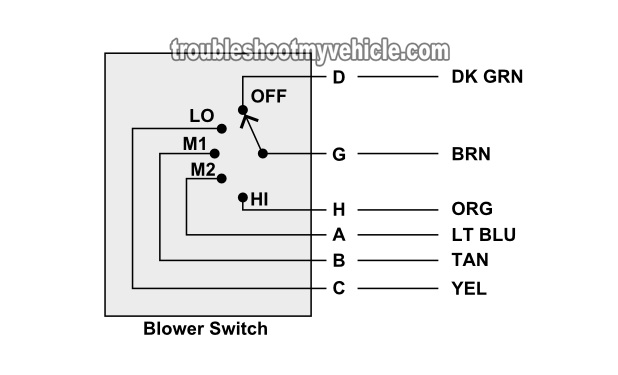
What this means in plain English is that as you turn the blower fan speed knob from OFF to any of the fan speeds (LO, M1, M2, and HI), the blower switch mechanically opens and closes the two contacts necessary to divert the incoming battery power (from circuit G) to the different circuits that'll get the blower fan speed you're choosing.
To really explain this and make it make more sense, let me give you an example of what happens when you turn the blower fan speed knob from OFF to LO:
- When the blower fan is in the OFF position:
- Battery power is available in terminal G of the blower switch connector.
- This battery power is channeled to terminal D of the blower switch harness connector.
- When you turn the blower fan switch to the LO position:
- Battery power is available in terminal G of the blower switch connector.
- This battery power is now interrupted from terminal D and diverted to terminal C of the blower switch harness connector.
- In tech speak: circuit G and D is now considered 'open' while circuit G and C is now considered 'closed'.
- The blower motor now runs in LO speed.
- This interruption and diverting of battery power goes on for all of the other blower fan speeds.
Since these are mechanical connections the blower switch is making to open and close these circuits, over time and use these contacts become pitted and covered in carbon (from the electrical arching that occurs when the contacts close). When this happens, one or several of the blower fan speeds stop working.
The cool thing is that diagnosing/troubleshooting the blower switch isn't hard. The following circuit descriptions will help:
| Blower Switch Circuit Descriptions | ||
|---|---|---|
| Pin | Wire Color | Description |
| A | LT BLU | M2 Speed Output. |
| B | TAN | M1 Speed Output. |
| C | YEL | LO Speed Output. |
| D | DK GRN | OFF Output. |
| E | -- | Empty |
| F | -- | Empty |
| G | BRN | Battery Power From Fuse. |
| H | LT BLU | M2 Input from AC-Heater Panel |
NOTE: There's a good chance that the color of the wires described above DOES NOT match what's on your particular vehicle. This is no cause for concern since the circuit descriptions are the same for all of the GM vehicles covered by this repair tutorial.
Where To Buy The Blower Switch And Save
You don't have to buy the whole A/C-Heater Control Panel to replace the blower control switch since the switch is removable. You can find the blower switch just about in anywhere. The best place to buy it, to save a few bucks, is online.
The following links will help you comparison shop for the blower motor control switch:
Disclosure: As an Amazon Associate, I earn from qualifying purchases. If my tutorials help you, using these links is an easy way to support the site at no extra cost to you. Thank you!
TEST 1: Checking Continuity Of The Blower Switch Fan Speeds
To find out if the blower switch is bad you can do two different tests.
One is to do a multimeter continuity test of the specific circuits that should be 'closed' when you turn the dial to the different blower motor speeds.
The other, explained in TEST 2, is to bypass the blower switch and indirectly test the blower switch.
In this test section I'll explain how to do the multimeter continuity test.
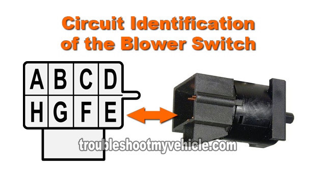
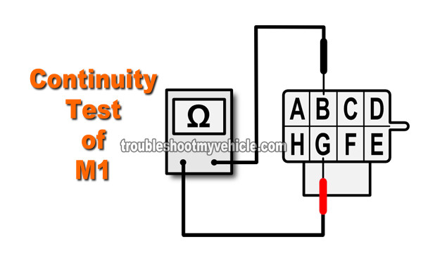
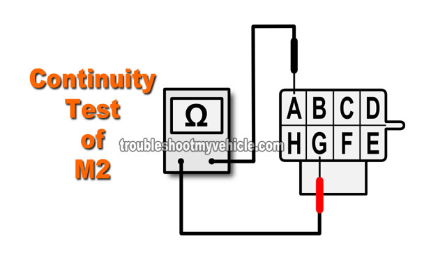
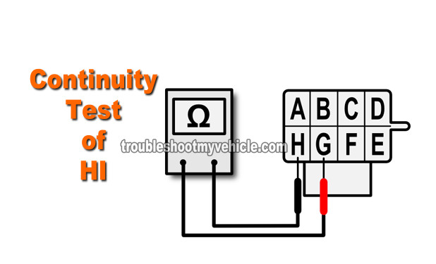
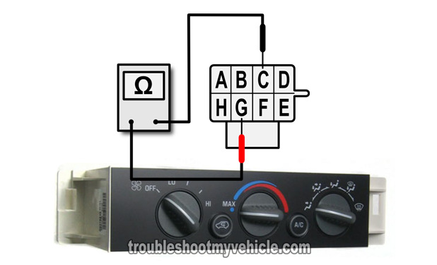
IMPORTANT: All multimeter continuity tests described in this test section are done on the blower switch's male spade metal terminals and not on the switch's connector. All the illustrations (in the image viewer) are of the blower switch itself and NOT of the connector (see image 6 of 6).
OK, these are the test steps:
- 1
Remove the A/C-Heater control panel from the dash and set your multimeter to Ohms mode (Ω).
Don't have a multimeter or need to upgrade yours? Check out my recommendation: Buying A Digital Multimeter For Automotive Diagnostic Testing (found at: easyautodiagnostics.com). - 2
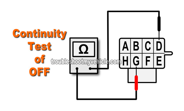
With the blower switch knob set to the OFF position.
You should have continuity between D and G (see image 1 of 6 to identify the proper male spade terminals to probe). - 3
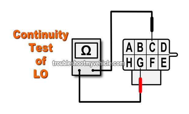
With the blower switch knob set to the LO position.
You should have continuity between C and G (see image 2 of 6 to identify the proper male spade terminals to probe). - 4
With the blower switch knob set to the M1 position.
You should have continuity between B and G (see image 3 of 6 to identify the proper male spade terminals to probe). - 5
With the blower switch knob set to the M2 position.
You should have continuity between A and G (see image 4 of 6 to identify the proper male spade terminals to probe). - 6
With the blower switch knob set to the HI position.
You should have continuity between H and G (see image 5 of 6 to identify the proper male spade terminals to probe).
Let's take a look at what your test results mean:
CASE 1: One or more of the circuits tested DID NOT have continuity when the blower fan speed knob was turned. Repeat the tests just to make sure of your test results.
If continuity is not present where indicated in the test steps above and this lack of continuity coincides with the blower fan speed that's not working on your pickup or SUV, then you've found the cause of the problem.
Replace the blower switch in the A/C-Heater control panel with a new one to solve the problem. To comparison shop for the blower control switch, take a look at this section here: Where To Buy The Blower Switch And Save.
CASE 2: All circuits tested had continuity where indicated in the test steps. This is good and is the correct and expected test result that tells you that the blower fan switch (in the A/C-Heater control panel) is OK.
Your next step is to bypass the blower resistor using a simple jumper wire. For this test go to: TEST 2: Using A Jumper Wire To Bypass The Blower Switch.

