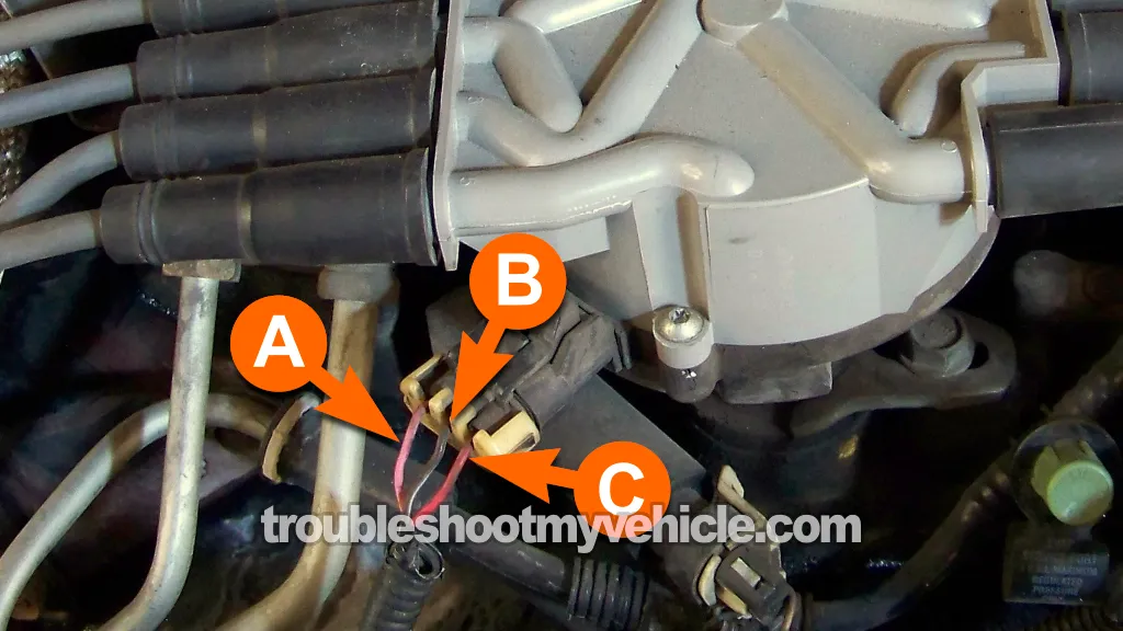
CMP TEST 2: Making Sure The CMP Sensor Is Getting Power

The cam sensor on your Chevy (or GMC or Olds or Cadillac) pick up, SUV, or mini-van is a Hall Effect type sensor, and as such, it needs an external power source (which in this case are 12 Volts) to be able to perform its function.
If these 12 Volts are missing, the cam sensor will not produce a cam signal.
This test step will help you to verify that 12 Volts are present or not. This is what you'll need to do:
- 1
Disconnect the CMP sensor from its 3-wire connector.
- 2
Place your multimeter in Volts DC mode.
- 3
With the red multimeter test lead, probe the female terminal that corresponds to the wire identified with the letter C.
- 4
Connect the black multimeter test lead to the battery negative (-) terminal.
- 5
Turn the key to the ON position.
- 6
If all is OK, your multimeter will display 10 to 12 Volts DC.
Now, let's take a look at what those voltage readings (or lack of) mean:
CASE 1: The multimeter showed 10-12 Volts. This multimeter test result confirms that the camshaft position sensor is getting power.
The next thing to do, is to check that the cam sensor has a good path to Ground. For this test, go to: CMP TEST 3: Making Sure The CMP Sensor Is Getting Ground.
CASE 2: The multimeter DID NOT show 10-12 Volts when the ignition was turned ON. This lack of power will keep the cam sensor from generating its cam signal.
With this test result, you have now eliminated the cam sensor on your 4.3L (or 5.0L or 5.7L) as the cause of the cam sensor code (P0340 Camshaft Position Sensor Circuit or P0341 Camshaft Position Sensor Performance). Solving this lack of 12 Volts, to the cam sensor, will get it back to working again.
CMP TEST 3: Making Sure The CMP Sensor Is Getting Ground

Since the cam sensor gets power (12 Volts DC) from an external source, these 12 Volts need a return path to Ground.
In this test step, you're gonna' verify that this Ground path does exist.
The wire (circuit) that provides this path to Ground is the one labeled with the letter A in the photo above.
A word of caution: This Ground is provided inside the PCM (Powertrain Control Module = Fuel Injection Computer) so be careful and do not short this circuit to power (12 Volts) or you risk damaging the PCM.
Let's get started:
- 1
Disconnect the CMP sensor from its 3-wire connector.
- 2
Place your multimeter in Volts DC mode.
- 3
With the black multimeter test lead, probe the female terminal that corresponds to the wire identified with the letter A.
- 4
Connect the red multimeter test lead to the battery positive (+) terminal.
- 5
Turn the key to the ON position.
- 6
If all is OK, your multimeter will display 10 to 12 Volts DC.
Now, let's take a look at what those voltage readings (or lack of) mean:
CASE 1: Your multimeter registered 12 Volts DC. This indicates that the camshaft position sensor has a good path to Ground. This test result confirms (in conjunction with the previous two) that the camshaft position sensor is bad. Replace the cam sensor.
To be a bit more specific, you have already checked that:
- The camshaft position sensor is not producing a cam signal (TEST 1).
- The camshaft position sensor is being fed with power (TEST 2).
- And, in this test, you have confirmed that the camshaft position sensor is getting Ground.
So, taking the above in consideration, you can conclude that the camshaft position sensor is bad and needs to be replaced.
CASE 2: Your multimeter DID NOT register 12 Volts DC . This missing Ground will keep the camshaft position sensor from producing a cam signal.
I suggest that you double-check all of your connections and re-test. If you still get the same result, you have now eliminated the cam sensor as bad, since without a good Ground path the cam sensor will not work.
Related Test Articles
There are several more GM 4.3L, 5.0L and 5.7L specific 'how to' tutorials that I've written for your troubleshooting and diagnostic benefit. The articles that are here in this web site you can find them at the GM Index of Articles and scrolling down to the 4.3L, 5.0L, 5.7L section. To go there now, click here: GM 4.3L, 5.0L, 5.7L Index Of Articles.
If you need to test the ignition system (like the ignition module, ignition coil, distributor cap, spark plug wires), you can find the step-by-step tests in the following two test articles (found at easyautodiagnostics. Com).
- How To Test A Misfire / No Spark-No Start Condition GM 4.3L, 5.0L, 5.7L Distributor Ignition System (1996-2004) (at: easyautodiagnostics.com).
- This article will help you to find the cause of a misfire or 'no-spark no-start' condition on your GM car, pickup, mini-van, van or SUV equipped with a 4.3L, or 5.0L, or 5.7L engine. The testing is explained step by step, making the whole diagnostic and troubleshooting as pain free as possible.
- How To Test GM Ignition Control Module 4.3L V6, 5.0L V8, and 5.7L V8 (1995 thru' 2005) (at: easyautodiagnostics.com).
- This is one of the easiest GM ignition control modules to test. This article will take you step by step through the whole process of diagnosing and troubleshooting a bad ignition control module and ignition coil.

If this info saved the day, buy me a beer!

