Is there a good chance that the PCM has fried and is the one causing the MAP sensor trouble code that NEVER goes away no matter what you do or replace? The sad answer is yes. I have diagnosed and repaired this specific problem quite a few times.
Is there a way to find out if the PCM has fried (and thus causing the MAP sensor code even though the MAP sensor is OK)? The answer is yes too!
There are two basic methods to test for a bad PCM. One is to replace it with another good unit and the other involves a process of elimination to come to the conclusion that the PCM is bad (or not).
Using the 'process of elimination' method, that I'm gonna' explain in detail in this tutorial, I've been able to successfully diagnose a bad PCM with about 95% accuracy.
Only 95% accurate? Not 100% accurate? I know, I know. Unfortunately, diagnosing a bad PCM is not an exact science but you'd be surprised how effective these tests can be at spotting problems that other-wise could have you replacing a good PCM (and throwing money down the drain).
IMPORTANT: Although the basic testing method described in this tutorial could be used with any vehicle, the illustrations, PCM pin identification, and MAP sensor pin identification APPLY ONLY to 1993 and 1994 4.3L, 5.0L, and 5.7L GM equipped pickups equipped with throttle body fuel injection (TBI) and the 4L60-E automatic transmission.
Contents of this tutorial:
Before You Start: Check The Basics
Quite a few things can fool the fuel injection computer into thinking the MAP sensor is bad when it isn't
Before you start thinking about testing (and/or replacing) the fuel injection computer (henceforth known as the PCM -Powertrain Control Module), you need to first:
- Bench test the MAP sensor.
- Confirm that the engine does not have any vacuum leaks.
- Confirm that the EGR valve is NOT stuck open.
- Confirm that the fuel pump is producing the correct fuel pressure (12 PSI) with a fuel pressure gauge.
- Confirm that all 6 or 8 cylinders have good compression.
I can't stress enough the importance of eliminating the MAP sensor (itself), a stuck-open EGR valve, the fuel pump, engine compression, and vacuum leaks as the source of the MAP sensor code... Why? So that you can avoid spending money on parts your pickup may not need.
The following tutorials will if you haven't checked the MAP sensor (itself) or engine compression:
- Diagnosing a Stuck Open EGR Valve (GM 4.3L, 5.0L, 5.7L).
- MAP Sensor Test (P0106, P0107, P0108) (GM 4.3L, 5.0L, 5.7L).
- How To Test The Engine Compression (GM 4.3L, 5.0L, 5.7L).
What's Involved In Testing For A Bad PCM?
Once the basics have been checked, how can you and I conclude the PCM is bad? By a process of elimination that involves checking these specific things:
- Making sure there is continuity in the wiring between the PCM and the MAP sensor.
- Making sure that the MAP sensor wires are not shorted to each other.
- Making sure that the MAP sensor wires are not shorted to Ground.
- That the PCM is getting power and Ground.
All of the above circuit tests aren't hard and I'll show you how in this tutorial.
OK, before we get started, it's important that you know that the PCM covered by this tutorial has two connectors. One PCM connector is red and the other is blue in color.
Each PCM connector has 32 slots and are identified by a number preceded by a letter prefix (e.g. B-4, B-13, E-14). The test steps, in this tutorial, will point out what specific PCM circuits you have to test in a detailed step-by-step way and with an illustration to boot.
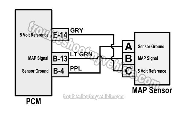
The MAP sensor circuits (wires) that we're gonna' be testing are:
- MAP sensor circuit A: PPL (purple) wire and it connects to the B-4 terminal of the red PCM connector.
- MAP sensor circuit B: LT GRN (light green) wire and it connects to the B-13 terminal of the red PCM connector.
- MAP sensor circuit C: GRY (gray) wire and it connects to the E-14 terminal of the blue PCM connector.
The PCM circuits we're gonna' be testing are:
- B-4 terminal of the red PCM connector: PPL (purple) wire and it connects to the MAP sensor circuit A.
- B-13 terminal of the red PCM connector: LT GRN (light green) wire and it connects to the MAP sensor circuit B.
- E-14 terminal of the blue PCM connector: GRY (gray) wire and it connects to the MAP sensor circuit C.
There a few other PCM circuits (for power and Ground) that we'll testing that I did not include in the list above, but you'll see them in TEST 4. To correctly identify the PCM terminals, the following 1993 PCM pin out chart will come in handy:
TEST 1: MAP Sensor Circuit Continuity Tests
To get the ball rolling, the first thing we need to do is to make sure that all three wires of the MAP sensor connector have continuity between it and the PCM connector.
In tech terms, we're gonna' make sure that the wires are not 'open'... because if they are, the signal that that wire carries will not make it to its destination (be it the PCM or the MAP sensor).
If you do find an 'open', then we can correctly conclude that a bad PCM is not behind the MAP sensor problem or trouble code.
The illustrations in the image viewer will help you to further identify the terminals you need to test.
IMPORTANT: It's super important that you do not probe the front of the PCM terminal (to check for continuity between it and the MAP sensor connector) or you will damage the metal terminal (inside the connector). You need to back-probe the terminal or use a wire piercing probe on the PCM connector wire. To see what a wire piercing problem looks like, go here: Wire Piercing Probe Tool Review (Power Probe PWPPPPP01).
These are the test steps:
- 1
Disconnect the battery negative (-) terminal. All tests in this section must be done with the battery disconnected from the battery negative cable.
- 2
Disconnect the 4L60-E automatic transmission from its electrical connector. Don't skip this step because the MAP sensor PPL wire also connects to the automatic transmission and this circuit needs to be completely isolated.
- 3
Disconnect the PCM and MAP sensor from their connectors. Check the connectors for any obvious problems (like damage) and repair if necessary.
IMPORTANT: Before disconnecting the PCM, touch any unpainted/clean metal surface on your vehicle to discharge any static electricity you may have stored on you. Static electricity can fry the PCM. - 4
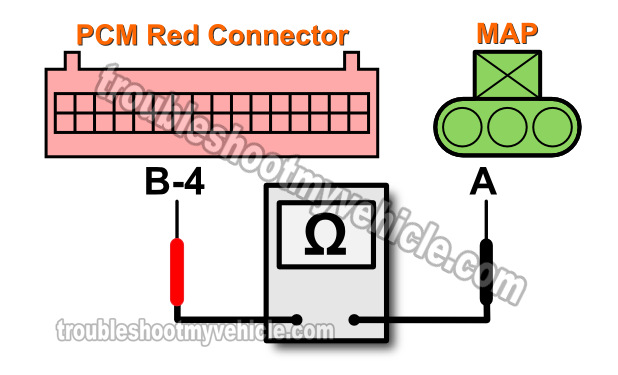
Check continuity between MAP sensor terminal A (PPL wire) and terminal B-4 of the red PCM connector using the appropriate tools (see image 1 of 3).
Continuity should be present (.5 Ohms or less). - 5
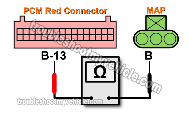
Check continuity between MAP sensor terminal B (LT GRN wire) and terminal B-13 of the red PCM connector using the appropriate tools (see image 2 of 3).
Continuity should be present (.5 Ohms or less). - 6
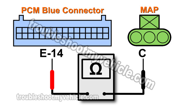
Check continuity between MAP sensor terminal C (GRY wire) and terminal E-14 of the blue PCM connector using the appropriate tools (see image 3 of 3).
Continuity should be present (.5 Ohms or less).
Let's take a look at what your test results mean:
CASE 1: Continuity was present in all MAP sensor circuits. This tells you that the wires are OK and are not 'open'.
The next step is to make sure that they are not shorted to Ground or each other. For this test, go to: TEST 2: Circuits Shorted To Each Other.
CASE 2: Continuity was not present in one or more circuits tested. Double check that you're testing the correct circuit(s) and repeat the tests.
If your multimeter still does not register continuity in the indicated circuit then that MAP sensor wire has a problem that needs to be solved and tells you that the problem IS NOT due to a bad PCM.
Repairing the 'open' in the wire that did not show continuity should solve the MAP sensor problem and trouble code.


