Testing the 1996-2000 1.6L Honda Civic automatic transmission's lock-up solenoid assembly is a whole lot easier than you think.
The two solenoid valves that make up the lock-up solenoid assembly are easily tested, and in this tutorial, I'm gonna' show you how in a step-by-step manner.
Contents of this tutorial:
START HERE: Lock Up Solenoid Assembly Tests
As you're already aware, the lock-up solenoid assembly on your 1996-2000 1.6L Honda Civic is made up of two solenoids.
One is identified as solenoid valve “B” and the other is identified as solenoid valve “A”.
Troubleshooting both of them isn't hard since both are tested in the same way. There are two basic tests for each solenoid that makes up the pack.
Here's a brief description of the 4 tests in this tutorial:
- resistance testing solenoid valve A..
- This test simply involves measuring the resistance of solenoid valve A and comparing the value with the factory spec of 14-25 Ohms.
- TEST 1: Shift Solenoid A Resistance Test.
- Manually applying 12 Volts to solenoid valve A.
- In this test, you'll use a jumper wire to apply power (from your Honda's battery) to shift solenoid A and listen for a clicking sound.
- TEST 2: Applying 12 V To Solenoid A.
- resistance testing solenoid valve B..
- This test simply involves measuring the resistance of solenoid valve B and comparing the value with the factory spec of 14-25 Ohms.
- TEST 3: Solenoid B Resistance Test.
- Manually applying 12 Volts to solenoid valve B..
- In this test, you'll use a jumper wire to apply power (from your Honda's battery) to solenoid valve B and listen for a clicking sound.
- TEST 4: Applying 12 V To Solenoid B.
TEST 1: Solenoid A Resistance Test
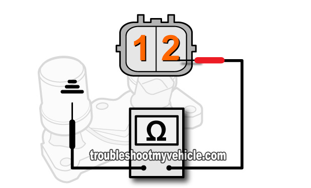
Solenoid valve B, of the lock-up solenoid valve assembly, gets power on terminal labeled with the number 2 of its connector.
It gets Ground thru' its metal base (the one that bolts down to the transmission's case).
So, to test solenoid valve B's resistance with your multimeter, you'll need to probe terminal number 2 and the solenoid assembly's metal base.
If you don't have a multimeter and need to buy one, check out my recommendations here: Buying A Digital Multimeter For Automotive Diagnostic Testing (at: easyautodiagnostics.com).
NOTE: Perform this test with a completely cold engine/transmission to avoid getting your hands burned.
OK, this is what you need to do:
- 1
Place your multimeter in Ohms mode.
- 2
Unplug the lock up solenoid assembly from its electrical connector.
NOTE: This test is done on the lock-up solenoid's connector AND NOT on the engine wiring harness' connector. - 3
Measure the resistance between terminal labeled with the #2, in the image viewer above, and the solenoid assembly's body.
NOTE: Shift solenoid A is Grounded by the solenoid assembly's case. If the solenoid assembly is still bolted to the transmission housing, you can Ground your multimeter's lead directly on the battery's negative (-) terminal. - 4
Your multimeter should read 14-25 Ohms for the resistance value of shift solenoid A.
Let's take a look at what your test results mean:
CASE 1: Solenoid valve A's resistance is between 14-25 Ohms. This test result confirms that the solenoid's internal resistance is within the factory specification.
Although the shift solenoid A passed this test, there's still one more we need to do, which is to manually apply power to the solenoid and see if it clicks. Go to: TEST 2: Applying 12 V To Shift Solenoid A.
CASE 2: Solenoid valve A's resistance WAS NOT between 14-25 Ohms. Recheck your multimeter test connections and retest. If you still don't get the correct resistance, then shift solenoid A is bad and you'll need to replace the entire lock-up solenoid valve assembly to solve the issue.


