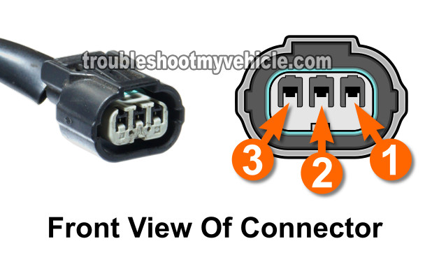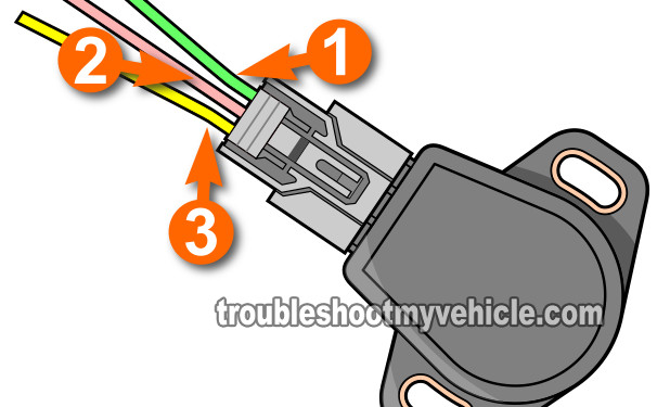
The throttle position sensor (TPS) on your 1.7L equipped Honda Civic can be accurately tested with just a multimeter and without having to remove it from its spot on the throttle body.
In this tutorial, I'll show you where you need to make your multimeter connections to test it and find out if it's bad (or not) and in the process troubleshoot the following diagnostic trouble codes:
- P0122: Throttle Position Sensor Circuit Low Input.
- P0123: Throttle Position Sensor Circuit High Input.
- P1121: Throttle Position Sensor Signal Lower Than Expected.
- P1122: Throttle Position Sensor Signal Higher Than Expected.
Contents of this tutorial:
![]() You can find this tutorial in Spanish here: Cómo Probar El Sensor de la Posición de la Mariposa (2001-2005 Honda 1.7L) (at: autotecnico-online.com).
You can find this tutorial in Spanish here: Cómo Probar El Sensor de la Posición de la Mariposa (2001-2005 Honda 1.7L) (at: autotecnico-online.com).
Basics Of The Throttle Position Sensor (TPS)

The throttle position sensor's job is to measure the angle of the throttle plate as you step on (and step off) the accelerator pedal since the throttle plate is connected to the accelerator pedal via the accelerator cable.
Your Honda Civic's PCM receives this throttle angle info on the middle wire. The other two provide power and Ground (to the TPS).
In the table below, you'll find a short description of what each wire does:
| 1.7L Honda Civic TP Sensor Circuits (2001, 2002, 2003, 2004, 2005) |
||
|---|---|---|
| Pin | Wire Color | Description |
| 1 | YEL/BLUE | 5 Volt Reference |
| 2 | RED/BLK | Throttle Plate Position Signal |
| 3 | GRN/YEL | Ground |
TEST 1: Checking The Throttle Position Sensor (TPS) Signal

The key to successfully diagnosing the TPS on your 1.7L Honda Civic is to know that as the throttle plate opens, the TPS produces a higher voltage.
And as the throttle plate closes back to its original position, the TP sensor outputs a decreasing voltage.
So, in this first test step, we're gonna' tap into the TP sensor harness connector's middle RED/BLK wire with a multimeter (set to Volts DC mode) and manually open and close the throttle plate to see if the sensor produces a decreasing/increasing voltage output.
If the TPS is bad, then the voltage output will stay stuck at one value.
IMPORTANT: This is an on car test of the sensor and the throttle position sensor must remain connected to its harness connector.
Here are the test steps:
- 1
Place your multimeter in Volts DC mode and connect the red test lead to the BLK/RED wire of the TP sensor harness connector.
NOTE: The TP sensor connector needs to be connected to the TPS, so you'll need to either back-probe the connector or use a wire piercing probe to get to the signal inside the wire (to see what a wire piercing probe looks like: Wire Piercing Probe Tool). - 2
Ground the black multimeter test lead directly on the battery negative (-) post.
- 3
Manually rotate the throttle.
You'll get the best results by opening and closing the throttle directly on the throttle body instead of stepping on the accelerator pedal. - 4
The multimeter should show an increasing voltage as you (or your helper) open up the throttle.
You'll get the best results by opening and closing the throttle directly on the throttle body instead of stepping on the accelerator pedal. - 5
The multimeter should show a decreasing voltage as you begin to close the throttle.
- 6
Using a screwdriver's handle, gently tap the TP sensor as you open and close the throttle and observer the multimeter.
The purpose (of tapping the TP sensor with the screwdriver's handle) is to see if the TP sensor shows gap's in the voltage signal. Why? Because a good TP sensor will show a continuous increasing or decreasing voltage signal even while getting tapped by the screw-driver's handle.
Let's interpret your test result:
CASE 1: The TP sensor signal's voltage increased and decreased smoothly and without gaps. This is the correct and expected TPS test result. This result tells you that the TPS is working correctly.
This test result also tells you that:
- Circuit #1 is providing power (5 Volts).
- Circuit #3 is providing Ground.
CASE 2: The TP sensor signal's voltage did not increase or decrease. In the majority of the cases this TPS result tells you that the sensor is bad. But not always.
To be sure that the TPS is truly fried, we need to do 2 more tests. These tests involve checking that the sensor is getting both power and Ground. For these tests, go to: TEST 2: Checking Throttle Position Sensor (TPS) Power And Ground.
CASE 3: The TP sensor signal's voltage showed gaps in its voltage output as you tapped the sensor with the screwdriver. If the gaps in the multimeter's voltage readings only showed up when you were tapping on the TPS (with the screwdriver's handle) then this test result tells you that the TPS is bad and needs to be replaced.

