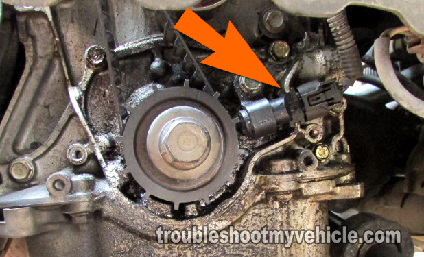
The crank sensor on your 1.7 liter equipped Honda Civic cannot be tested with a simple multimeter resistance (Ω) test. It has to be tested in action.
Thankfully, testing the crankshaft position sensor on your 2001-2005 1.7L Honda Civic isn't difficult and it does not have to be removed to be tested.
If you think that it has failed and causing you Civic to no start, then this tutorial will help you to test it with a multimeter in a step-by-step manner
Contents of this tutorial:
NOTE: The following wiring diagram may be of help in your crank sensor diagnostic: 2001-2005 Crank Sensor Wiring Diagram (Honda 1.7).
![]() You can find this tutorial in Spanish here: Cómo Probar El Sensor De La Posición Del Cigüeñal (2001-2005 1.7L Honda Civic) (at: autotecnico-online.com).
You can find this tutorial in Spanish here: Cómo Probar El Sensor De La Posición Del Cigüeñal (2001-2005 1.7L Honda Civic) (at: autotecnico-online.com).
Symptoms Of A Bad Crankshaft Position Sensor
The most obvious symptom that your Honda Civic will experience, when the crank sensor fails, is a ‘cranks but does not start condition’.
The fuel injection computer on your Honda Civic is designed to sense when the crankshaft position (CKP) sensor is bad and set one of the following diagnostic trouble codes.
- P0335: CKP Sensor No Signal.
- P0336: Crank Sensor Intermittent Interruption.
- P0340: Crank Sensor Intermittent Interruption.
But this doesn't always happen. There are times when the crank sensor has failed (and causing your Honda Civic to crank but not start) yet the fuel injection computer does not set a code. When this happens, the two symptoms that you can count on seeing are:
- No fuel injector pulses (when tested with a Noid light).
- No spark from any of the 4 ignition coils (when tested with a spark tester).
So far, the above symptoms describe a crank sensor that has completely failed. Unfortunately, there are times that when the crank sensor fails, it fails intermittently.
Intermittent failures, of the crank sensor, are some the hardest to diagnose due to the fact that the sensor works fine most of the time. And it usually isn't failing when you are testing it, leading you to believe that the sensor is fine.
NOTE: If your Honda Civic is stalling intermittently in your particular case, you have to wait till your Honda Civic ‘cranks but does not start’ to be able to check the crank sensor. A clear indication that the crank sensor is working fine (and can't be tested at the moment) is your Honda Civic starting and staying running.
Crankshaft Position Sensor Circuit Descriptions

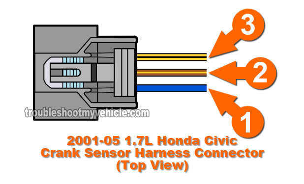
The crankshaft position (CKP) sensor on your 2001-2005 1.7L equipped Honda Civic has 3 wires coming out of its harness connector.
Each wire is color coded and carries a specific signal and knowing which type will help you test the sensor.
Using the illustration of the crank sensor connector (in the image viewer on the left), here are the circuit descriptions of the three wires of the crankshaft position (CKP) sensor connector that I'll be using in this tutorial.
| Crank Sensor Circuit Descriptions 2001-2005 Civic EX, DX, LX |
||
|---|---|---|
| Pin | Wire Color | Description |
| 1 | BLU | Signal. Feeds the PCM with the signal the crank sensor creates. |
| 2 | BRN/YEL | Ground. Feeds the crank sensor with chassis Ground. |
| 3 | YEL/BLK | Power. Feeds the crank sensor with power (12 Volts DC) from PGM-FI main relay 1. |
NOTE: You can find the crank sensor wiring diagram here: 2001-2005 Crank Sensor Wiring Diagram (Honda 1.7).
TEST 1: Verifying The Crank Signal With A Multimeter

The very first thing that we'll do to find out if the crank sensor is bad or not is too check to see if it's creating a crank signal when you turn over the engine by hand.
This signal is an ON/OFF voltage signal. Specifically: ON is when the multimeter displays 5 Volts DC and OFF is when it displays 0 Volts (.2 volt equals 0 Volts).
The way that I am going to show you how to test the crank sensor is a very accurate way. But this accuracy depends on you turning the engine over by hand, which means using a half inch ratchet wrench and the appropriate socket to turn the crankshaft pulley by hand.
IMPORTANT: Before you start this test you must disconnect all of the ignition coils from their harness connectors. This safety precaution will keep the car from starting.
Here are the test steps:
- 1
Jack up your Honda Civic and place it on jack stands (to gain access to the crank sensor). Once on jack stands, remove the driver side water splash shield.
- 2
Disable the ignition system by disconnecting each individual ignition point from its harness connector.
By disabling the ignition coils you will keep the vehicle from accidentally starting as you perform the crank sensor test. - 3
Disconnect the crank sensor connector and connect the red multimeter test lead to the BLU (blue) wire on the connector. The BLU wire connector is the one that transmits the signal (the cranks sensor creates) to your Honda's PCM.
The BLU wire is the one labeled with the number 1 in the illustration in the image viewer.
NOTE: You need to use a tool like a wire piercing probe (or a back probe) to connect your multimeter's red test lead to the BLU wire of the crank sensor connector. To see what a what this tool looks like, click here: Wire Piercing Probe. - 4
Place your multimeter in Volts DC mode since the signal the crank sensor creates is an ON/OFF 5 Volts DC pulse.
- 5
Connect the black multimeter test lead to a good Ground point on the engine. Or better yet, Ground the black test lead directly to the negative (-) battery terminal using a jump start cable.
- 6
Reconnect the connector back to the sensor and turn the key to the On position (position II) but don't crank the engine. This will power up the crank sensor with the voltage and Ground we need to test it in action.
- 7
Using a 1/2 ratchet and a 19 mm socket, turn the crank pulley clockwise by hand.
IMPORTANT: For the accuracy of this test the crankshaft pulley must be turned by hand. Using the starter motor to turn the engine will not give you the results indicated in this tutorial. - 8
Your multimeter will register an ON/OFF voltage signal (if the sensor is OK). ON is when the multimeter displays 5 Volts DC and OFF is when it displays 0 Volts (.2 volt equals 0 Volts).
Let's interpret your test result:
CASE 1: The multimeter registered the ON/OFF 5 Volts crank signal as you turned the engine with the ratchet. This is good, since it means that the crank sensor is working properly and creating the signal.
No further testing is required since the other two tests in this article check that the crankshaft position (CKP) sensor is getting power and Ground. Since your test confirms that the CKP sensor is creating a signal, then it also proves that it's getting power and Ground.
CASE 2: The multimeter DID NOT register the ON/OFF 5 volt crank signal as you turned the engine with the ratchet. This test result usually confirms that the crank sensor is bad and needs to be replaced. About 90% of the time this is hitting the nail on the head, but I recommend that you check that the sensor is also getting power and Ground too.
By testing and confirming that the CKP sensor is getting power and Ground, you'll be able to decisively confirm it is bad or that maybe another issue exists. For the next steps, go to: TEST 2: Checking Power And Ground Circuits.

