In this tutorial I'll show you how to test the throttle position sensor (TPS) on your 4.9L L6 equipped Ford with a simple multimeter.
You'll be surprised just how easy it is to find out if the throttle position sensor (TPS) is bad or not.
And the best part is that you don't have to remove it to test it since the test I'm gonna' show you is done with the throttle position sensor (TPS) in place on the throttle body.
Contents of this tutorial:
- Symptoms Of A Bad Throttle Position Sensor (TPS).
- Basics Of The Throttle Position Sensor (TPS).
- START HERE: Throttle Position Sensor (TPS) Tests.
- TEST 1: Checking The Throttle Position Sensor (TPS) Signal.
- TEST 2: Checking Throttle Position Sensor (TPS) Power And Ground.
- Throttle Position Sensor (TPS) Is Good But Code Won't Go Away.
- More ‘How To Test’ Tutorials.
![]() You can find this tutorial in Spanish here: Cómo Probar El Sensor TPS (1988-1995 Ford 4.9L) (at: autotecnico-online.com).
You can find this tutorial in Spanish here: Cómo Probar El Sensor TPS (1988-1995 Ford 4.9L) (at: autotecnico-online.com).
Symptoms Of A Bad Throttle Position Sensor (TPS)
The throttle position sensor (TPS) is one of those sensors that the fuel injection injection can't live without. When this TP sensor fails, the fuel injection computer won't be able to effectively control the amount of fuel injection or timing advance and you're gonna' feel it as you drive your vehicle down the road.
Here a other symptoms of a bad throttle position sensor your Ford vehicle may experience:
- Trouble codes lighting up the check engine light (CEL):
- Code 23: Throttle Position (TP) Circuit Performance Problem.
- Code 53: Throttle Position (TP) Circuit High Input.
- Code 63: Throttle Position (TP) Circuit Low Input.
- Hesitation when accelerating the pick-up (van or SUV).
- Intermittent lack of power when accelerating.
- Bad gas mileage.
- Extended cranking time.
- Idle lopes (idle RPMs go up and down).
Basics Of The Throttle Position Sensor (TPS)

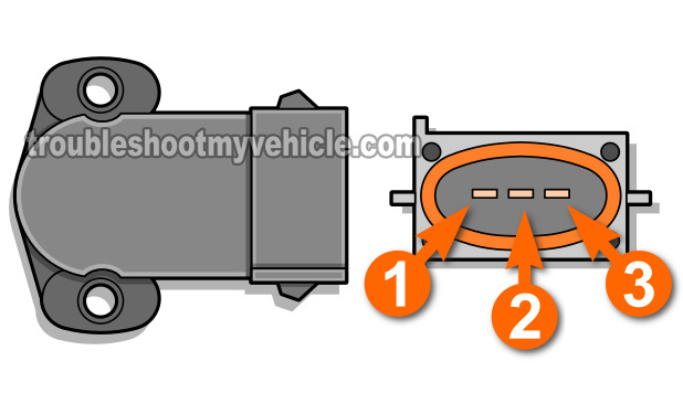
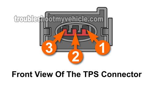
As you're already aware, the throttle position sensor (TPS) on your 4.9L equipped Ford has 3 wires coming out of its connector.
Each wire starts and ends at the fuel injection computer (known in today's tech lingo as the Powertrain Control Module = PCM).
Each one carries a specific type of signal and in this section I'll briefly go over each one.
NOTE: I didn't include the color of the wires because they'll be different for each Ford covered by this tutorial. But don't worry, the circuits are the same regardless of the color of the wires or your specific model (as long as they're covered by this tutorial -see the ‘Applies To:’ box on the right).
TPS circuit descriptions:
- Circuit labeled 1:
- Ground (provided by the PCM).
- Circuit labeled 2:
- Throttle Position (TP) Signal Circuit.
- The TP signal's voltage increases as the throttle angle increases.
- The TP signal's voltage decreases as the throttle angle decreases.
- Circuit labeled 3:
- Power in the for of 5 Volts DC (provided by the PCM).
START HERE: Throttle Position Sensor (TPS) Tests
Here's a brief description of the test I'll be showing you in this tutorial.
All of them are very simple and easy but you do need to keep in mind the following safety precautions:
- The TP sensor has to remain connected to its connector for the tests to work. This is because the connector will provide both power and Ground (with the Key On Engine Off) for us to test the sensor.
- All three TP sensor wires connect directly to the PCM, so be careful and don't short them to 12 Volts or you'll fry the computer.
- The TP sensor test is done with the Key On Engine Off (KOEO).
The tests in this tutorial are:
- Checking that the TPS is producing a increasing/decreasing voltage signal.
- This test simply involves connecting your multimeter to the correct TP sensor wire and manually opening the throttle as observe the voltage reading the sensor is creating.
- TEST 1: Checking The Throttle Position Sensor (TPS) Signal.
- Checking that power and Ground are being fed to the TP sensor.
- In this test, you'll check that the TP sensor is getting both power and Ground (test done with a multimeter too).
- TEST 2: Checking Throttle Position Sensor (TPS) Power And Ground.

