TEST 3: Making Sure The Voltage Regulator Is Getting Power

For our last test, we're gonna check that the alternator's voltage regulator is getting power.
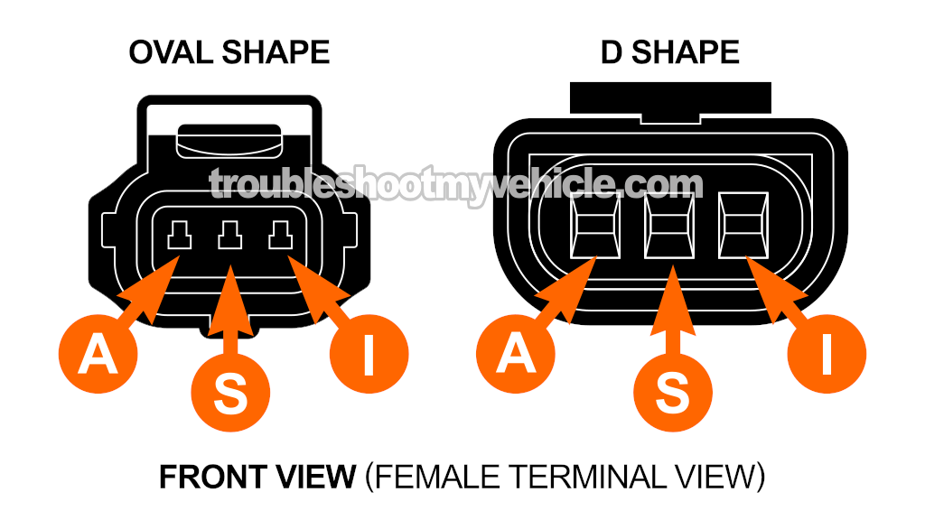
Depending on the year of your specific vehicle, the voltage regulator (which is located on the rear of the alternator itself) has a 3-wire or a 2-wire connector. Here are the specifics:
- 1995-1997 vehicles: The connector that connects to the voltage regulator is known as the D-Shape connector (see illustration above).
- 1998-2003 vehicles: The connector is known as the Oval Shape connector (see illustration above).
The wire that delivers power to the voltage regulator on both types of connectors is the yellow with white stripe (YEL/WHT) wire of its 3-wire or 2-wire connector.
The YEL/WHT wire get its power from a fuse located in the engine compartment fuse box. Here are the specifics:
- 1995-1997: STR ALT Fuse (in engine compartment fuse box).
- 1998-2002: Fuse 2 (in engine compartment fuse box).
- 2003: Fuse 101 (in engine compartment fuse box).
Alright, let's begin:
- 1
Reconnect the negative (-) battery cable to the battery's negative (-) post,.
- 2
Disconnect the 3-wire pigtail connector from the alternator.
This 3-wire connector connects to the alternator's voltage regulator. - 3
Connect the black multimeter test lead to the battery negative (-) terminal.
IMPORTANT: The multimeter test lead must connect to a clean spot on the battery's negative (-) terminal. - 4
Connect the red multimeter test lead to the female terminal labeled with the letter A of the alternator's 3-wire or 2-wire pigtail connector (see the illustration above).
NOTE: The wire connecting to terminal A should be the YEL/WHT wire. - 6
Your multimeter should register 10 to 12 Volts DC.
NOTE: Power is present at all times, no need to turn the key to the ON position.
Let's interpret your test result:
CASE 1: 10 to 12 Volts are present. This means that the alternator's voltage regulator is getting power.
You can conclude that the alternator is bad and needs replacement if you have:
- Confirmed that the battery's voltage drops to 10 Volts with the engine running and all accessories on (TEST 1).
- Confirmed that the BAT + circuit wire has continuity between the alternator and the battery positive (+) post (TEST 2).
- In this test section, confirmed that the voltage regulator is getting 10 to 12 Volts DC.
CASE 2: 10 to 12 Volts ARE NOT present. This tells you that the voltage regulator isn't getting power.
Without this voltage (10 to 12 Volts), the alternator won't activate. Your next step is to check the fuse, replace it if it's blown, and then repeat TEST 1.
More 4.6L Crown Vic And Grand Marquis Tutorials
There are quite a few 4.6L Ford Crown Victoria (Mercury Grand Marquis) 'how to' tutorials and wiring diagrams in this index:
E-Series Vans: You can find all of the available tutorials and wiring diagrams for the 4.6L and 5.4L V8 E-Series vans in this index:
F-Series Pickups: You can find all of the available tutorials and wiring diagrams for the 4.6L And 5.4L V8 F-Series pickups in this index:
- 4.6L, 5.4L Ford F150, F250, And F350 Index of Articles (at: easyautodiagnostics.com.com).

If this info saved the day, buy me a beer!

