
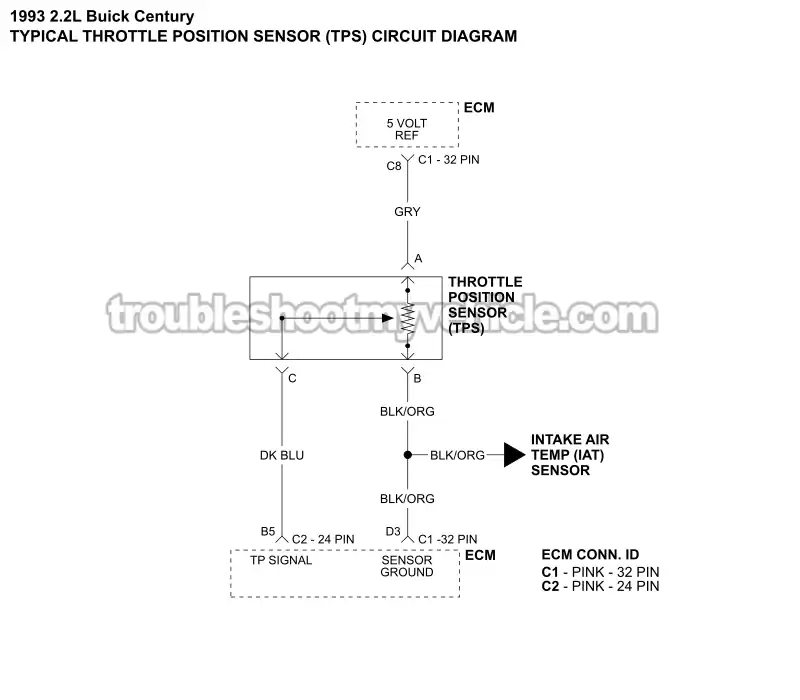
APPLIES TO: This throttle position sensor (TPS) circuit wiring diagram applies to the following vehicles:
- 2.2L Buick Century: 1993.
Basic Operating Theory Of The Throttle Position Sensor
The throttle position sensor (TPS) is mounted on the side of the throttle body, opposite the throttle lever. Its job is to let the Powertrain Control Module (PCM) know exactly how far the throttle plate is open as you press down or let up on the accelerator pedal.
The TPS is nothing more than a variable resistor (potentiometer). It has three electrical circuits:
- 5-Volt Reference: The PCM supplies the TPS with a regulated 5-Volt reference signal.
- Ground: The PCM also supplies the sensor with a Ground circuit.
- Signal: The TPS sends a voltage signal back to the PCM that changes as the throttle plate opens and closes.
With the ignition key in the ON position and the throttle plate closed (idle position), the TPS signal will usually be somewhere between 0.2 and 0.9 Volts DC. As the throttle plate begins to open, the signal voltage should increase smoothly. At wide-open throttle (WOT), the signal should be close to 5 Volts DC.
The PCM uses this changing voltage signal to determine how much the throttle plate is opening (driver demand). It uses this information to calculate fuel delivery and make other engine management decisions.
If the TPS signal becomes erratic, gets stuck at one voltage, or disappears completely, the PCM can no longer determine the correct throttle position. Depending on the model year of your 2.2L Buick Century, this can set one or more throttle position sensor trouble codes and cause noticeable driveability problems such as hesitation, unstable idle, poor acceleration, or even engine stalling.
The good news is that the TPS is one of the easiest sensors on the engine to test. Using nothing more than a multimeter, you can verify that the sensor is producing the correct voltage signal and that it's receiving both its 5-Volt reference signal and Ground from the PCM.
TPS SENSOR TEST: How To Test The TPS With A Multimeter (1993-1996 2.2L Buick Century).
Other TPS Sensor Wiring Diagrams
- TPS Sensor Circuit Wiring Diagram (1994-1995 2.2L Buick Century).
- TPS Sensor Circuit Wiring Diagram (1996 2.2L Buick Century).
More 2.2L Buick Century Tutorials
You can find a complete list of 2.2L Buick Century tutorials and wiring diagrams in this index:
Here's a sample of the tutorials you'll find in the index:
- How To Test For A Blown Head Gasket (1993-1996 2.2L Buick Century).
- How To Test Engine Compression (1993-1996 2.2L Buick Century).
- How To Test The TPS With A Multimeter (1993-1996 2.2L Buick Century).
- How To Test The MAP Sensor (1993-1996 2.2L Buick Century).

If this info saved the day, buy me a beer!
