Testing the front (upstream) oxygen sensor on your 3.8L Buick (Chevy, Olds, or Pontiac) vehicle is a pretty easy thing.
In this tutorial, I'll show you how to test the upstream oxygen sensor in a step-by-step way. Your test result will tell you if the O2 sensor is bad or not.
This sensor sensor is known by several different names: Bank 1 Sensor 1, upstream oxygen sensor, oxygen sensor before the catalytic converter, pre-catalytic converter oxygen (O2) sensor, or front oxygen (O2) sensor.
Before you start testing/troubleshooting codes P0135, I recommend that you take a look at the following oxygen sensor test primer:
- Testing P0135, P0141 O2 Heater Performance Problem.
- This article answers a lot of the most common questions like:
- What are the symptoms of a bad oxygen sensor heater element.
- Where are the O2 sensors located?
- What tools do I need?
- What does the heater inside the oxygen sensor do?
- This article answers a lot of the most common questions like:
- Testing Trouble Code: P0135 (GM 3.8L 1997-2003).
- This tutorial covers testing a P0135 Trouble Code on GM 3.8L 1997-2003 model vehicles.
Contents of this tutorial:
Circuit Descriptions Of The Upstream Oxygen Sensors

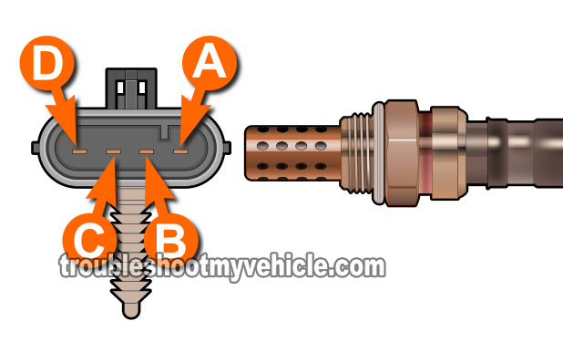
The Bank 1 Sensor 1 oxygen sensor has 4 wires. Each wire has a specific job to do.
2 of those 4 wires are the ones that provide power and Ground to the heater element inside the oxygen sensor.
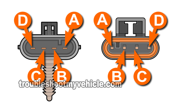
Identifying those 2 wires is aided by the fact that GM has labeled each one with a letter. These letters are: A, B, C, and D. Also, GM has embossed these letters on the oxygen sensor connector.
The two circuits (wires, that is), that we need to concern ourselves with are the ones labeled with the letter C and D.
In the chart below, is a short description of what each circuit does and the color of the wire. Now, in case the wire color doesn't match those of the upstream O2 sensor on your specific vehicle, there's no need to worry, because you can still identify the correct circuit by the letter embossed on the oxygen sensor connector.
| O2 Bank 1 Sensor 1 Circuits | ||
|---|---|---|
| Pin | Wire Color | Description |
| A | Tan | HO2S Low Signal |
| B | Purple w/ White stripe | HO2S High Signal |
| C | Black w/ White stripe | Heater Element Ground (Provide by PCM) |
| D | Pink | Heater Element 12 Volts (O2 sensor fuse) |
Where To Buy The Oxygen Sensor And Save
You could buy the upstream oxygen sensor at your local neighborhood auto parts store but if you call them and price it, it's gonna' cost a lot more than the buying them online.
Check out the link below and compare:
Disclosure: As an Amazon Associate, I earn from qualifying purchases. If my tutorials help you, using these links is an easy way to support the site at no extra cost to you. Thank you!
TEST INFO: The Basics Of Testing The Oxygen Sensor Heater Element
The very first thing we need to do, is to verify that the upstream sensor sensor's heater element is getting voltage.
You'll test this voltage with the key ON, but engine OFF. The amount of voltage your multimeter should record will be between 10 to 12 Volts DC.
The next step, after confirming that voltage is present, is to make sure that Ground is also present.
Here are some more specifics:
- Power is provided by the D circuit wire.
- This wire will be the Pink one, regardless of the type of O2 sensor GM has installed on your vehicle.
- Ground is provided by the C wire.
- This wire is usually a Black wire.
Making sure that the upstream oxygen sensor is getting both power and Ground are the two first basic tests we need to do.
Now, if both power (10 to 12 Volts DC) and Ground are present, then the next step (and the last test), is to measure the resistance of the heater element inside the oxygen (O2) sensor to see if it's fried or not.
This last resistance test you'll do with your multimeter in Ohms (Ω) mode and, depending on the result, you'll know if the heater element (within the upstream O2 sensor) is fried or not.
As you can see, testing the O2 sensor before the catalytic converter, to see if it's bad or not, is not hard to do at all. OK, in the next few pages are the step-by-step testing instructions you'll need to get to the bottom of the problem.


