The electronic throttle body looks like something that simply can't be tested, but nothing could be further from the truth! I can tell you from personal experience that it's one of the easier components to test on your Chevy Express or GMC Savana van.
In this tutorial, I'll explain a super easy way to test it that I've using for many years. With your test results, you'll quickly find out if it's good or bad.
I'm also including a ton of information that'll help you figure out how the throttle body works and will help you understand the 'why' of the tests I'm describing in this tutorial.
Contents of this tutorial:
- Symptoms Of A Bad Electronic Throttle Body
- What Tools Do I Need To Use To Test The Throttle Body
- What Does The Electronic Throttle Body Do?
- Electronic Throttle Body Terminal Pin Out Chart.
- Where To Buy The Electronic Throttle Body And Save
- TEST 1: Testing TPS 1 With A Multimeter
- TEST 2: Testing TPS 2 With A Multimeter
- TEST 3: Testing The TAC Motor
- More Chevy Express/GMC Savana Articles And Tutorials
APPLIES TO: This tutorial applies to the following vehicles:
- Chevrolet Express 1500 5.3L: 2007.
- Chevrolet Express 2500 6.0L: 2004, 2005, 2006.
- Chevrolet Express 3500 4.8L: 2007.
- Chevrolet Express 3500 6.0L: 2004, 2005, 2006, 2007.
- GMC Savana 1500 5.3L: 2007.
- GMC Savana 2500 4.8L: 2007.
- GMC Savana 2500 6.0L: 2004, 2005, 2006, 2007.
- GMC Savana 3500 4.8L: 2007.
- GMC Savana 3500 6.0L: 2003, 2004, 2005, 2006, 2007.
Symptoms Of A Bad Electronic Throttle Body
When the electronic throttle body in your Chevy Express or GMC Savana van fails, you might notice a few of the following symptoms:
- Reduced Engine Power: One of the most noticeable signs is a reduction in engine power. Your van might feel sluggish or struggle to accelerate, especially when you throw the transmission in Drive and step on the gas pedal.
- Stalling or Rough Idling: A faulty throttle body can cause the engine to stall or idle roughly. You might experience fluctuations in RPM or even sudden stalling when coming to a stop.
- Check Engine Light: If the throttle body is malfunctioning, it'll definitely trigger the check engine light on your dashboard. You'll see one of the following throttle position sensor 1 and 2 diagnostic trouble codes:
- P0120: Throttle Position (TP) Sensor 1 Malfunction
- P0220: Throttle Position (TP) Sensor 2 Malfunction
- Unresponsive Acceleration: When you press the gas pedal, you might notice a delay or lack of response from the engine.
- Erratic Throttle Response: Sometimes, a faulty throttle body can cause erratic behavior in throttle response. You might experience sudden surges of power or difficulty maintaining a steady speed.
What Tools Do I Need To Use To Test The Throttle Body
You don't need a scan tool to test the electronic throttle body on your Express or Savana van (although it's a plus if you have one).
To follow this guide, the most important tools you'll need are an analog multimeter and insulated jumper wires.
Why an analog multimeter? Because the sweep of the analog multimeter's needle makes it easier to spot a hiccup in the TPS's resistance change, which could indicate a problem.
A digital multimeter (DMM), while highly accurate and great for most tasks, won't display these quick, subtle changes in resistance as effectively. Its digital display updates with numerical values, which can jump quickly and make it harder to notice a brief or slight irregularity in the resistance pattern.
The cool thing is that analog multimeters are not expensive. Here are my recommendations:
Disclosure: As an Amazon Associate, I earn from qualifying purchases. If my tutorials help you, using these links is an easy way to support the site at no extra cost to you. Thank you!
What Does The Electronic Throttle Body Do?
In a nutshell, the electronic throttle body's job is to open/close the throttle plate when you step on/off the gas pedal. Although I won't go into minute technical detail, I'll go over some of the basics that'll help you understand how it works -info that'll also help make sense of the tests you'll be doing.
Unlike the old style setups with a physical accelerator cable connecting the accelerator pedal to the throttle plate, the Express and Savana vans covered by this tutorial use a drive-by-wire system that opens/closes the throttle plate without a direct mechanical link between them.
This drive-by-wire system is called the Throttle Actuator Control (TAC) system and it relies on the following components to operate the throttle plate:
- Throttle position sensor (TPS) 1.
- Throttle position sensor (TPS) 2.
- Accelerator pedal position (APP) sensor 1.
- Accelerator pedal position (APP) sensor 2.
- Throttle actuator motor.
- Throttle Actuator Control (TAC) module.
When you step on or off the accelerator pedal, the accelerator pedal position (APP) sensors take note and relay this info to the TAC module.
Based on the APP sensor inputs, the PCM then adjusts the throttle opening via a motorized actuator located inside the throttle body to match the amount of throttle you're trying to give the engine.
As the throttle actuator motor opens/closes the throttle plate, both throttle position sensors (which are located inside the throttle body and are constantly tracking the position of the throttle plate) relay this data to the PCM.
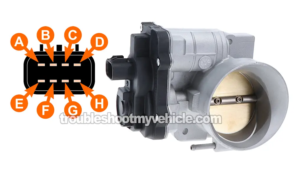
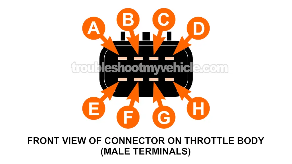
Electronic Throttle Body Terminal Pin Out Chart

| Electronic Throttle Body Connector Pin outs | ||
|---|---|---|
| Pin | Wire Color | Description |
| A | YEL | TAC Motor Control 1 |
| B | BLK/WHT | Low Reference (Sensor Ground - TP Sensor 2) |
| C | BRN | TAC Motor Control 2 |
| D | BLK | Low Reference (Sensor Ground - TP Sensor 1) |
| E | LT BLU/BLK | 5 Volt Reference ( TP Sensor 2) |
| F | PPL | TP Sensor 2 Signal |
| G | DK GRN | TP Sensor 1 Signal |
| H | GRY | 5 Volt Reference ( TP Sensor 1) |
- BLK = Black
- BLK/WHT = Black with white stripe wire
- BLU = Blue
- BRN = Brown
- DK GRN = Dark green
- LT BLU/BLK = Light blue with black stripe wire
- PPL = Purple
- WHT = White
- YEL = Yellow
The connector on the throttle body itself has male spade terminals. The terminals on the electrical connector are female terminals.
You'll perform all of the tests (in this tutorial) on the male spade terminals of the connector of the throttle body itself.
Where To Buy The Electronic Throttle Body And Save
The following links will help you comparison shop for the electronic throttle body:
Disclosure: As an Amazon Associate, I earn from qualifying purchases. If my tutorials help you, using these links is an easy way to support the site at no extra cost to you. Thank you!
Not sure if the electronic throttle body will fit your particular GM vehicle? Don't worry, once you get to the site, they'll make sure it fits. If it doesn't, they'll find you the right one.
TEST 1: Testing TPS 1 With A Multimeter

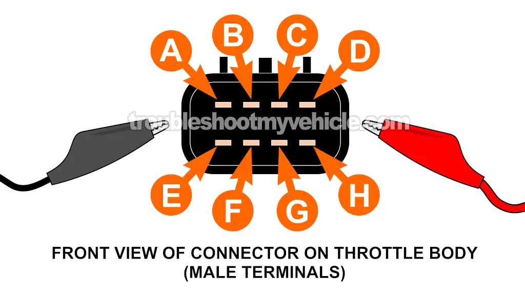
In this test section, we'll test the resistance between terminal G and terminal H as we open and close the throttle plate.
What we need to see is the resistance value decrease as the throttle plate is opened and then increase as we close it.
Another important thing, the resistance value should decrease/increase as you open/close the throttle plate without any gaps in the reading.
If TPS 1 is defective, you'll see that the resistance reading does not decrease as you open the throttle plate or you'll see gaps in the reading as you open/close the throttle plate.
To connect your multimeter test leads to the male terminals on the throttle body, I recommend that you use insulated jumper wires. You can see and example of these insulated wires here (and you can also buy them here): 10 Pc. And 5 Color Insulated Alligator Clips (at: amazon.com).
IMPORTANT: For the accuracy of the TPS resistance test, you should use an analog multimeter. If you don't have one, you can use a digital multimeter that has a bar graph in Ohms mode. A digital multimeter (without a bar graph) isn't able to respond fast enough to the changes in throttle plate movement and will show gaps in the values. These gaps could lead you to believe the sensor is bad when it isn't.
These are the test steps:
- 1
Disconnect the throttle body from its electrical connector.
- 2
Place your multimeter in Ohms mode.
- 3
Connect one multimeter test lead to terminal G.
NOTE: All connections are done on the male spade terminals of the connector of the throttle body itself. - 4
Connect the other multimeter test lead to terminal H.
- 5
The multimeter should show around 4 K Ohms Ω.
- 6
Slowly open the throttle plate by hand till it reaches its wide-open throttle (WOT) position.
- 7
The multimeter should show the resistance decreasing as you open the throttle plate.
NOTE: The multimeter's needle should move smoothly and steadily across the scale as you open the throttle plate. - 8
Slowly close the throttle plate to its closed position.
- 9
The resistance value should increase
NOTE: The multimeter's needle should move smoothly and steadily across the scale as you close the throttle plate. - 10
Gently push down and completely close the throttle plate.
- 11
The resistance value should continue to decrease as you completely close the throttle plate.
Let's examine your test results:
CASE 1: The multimeter's needle moved smoothly and steadily across the scale without any drops as you opened/closed the throttle plate. This is the correct test result and it lets you know that TPS 1 is OK (not defective).
The next test is to test TPS 2. For this test go to: TEST 2: Testing TPS 2 With A Multimeter.
CASE 2: The multimeter's needle DID NOT move across the scale as you opened/closed the throttle plate. This lets you know that TPS 1 is bad. You'll need to replace the throttle body unit.
CASE 3: The multimeter's needle moved across the scale but dropped (jumped) as you opened/closed the throttle plate. This lets you know that TPS 1 is bad. You'll need to replace the throttle body unit.


