TEST 2: Manually Inducing A Rich Condition


You've reached this point because in TEST 1 you confirmed that the right (or left) upstream oxygen sensor is stuck producing a continuous voltage (when it should be alternating between 0.2 and 0.8 Volts).
The next step is to manually induce a rich condition by spraying carburetor spray into a vacuum hose while the engine runs.
If the right (or left) upstream oxygen sensor on your Nissan Pathfinder is working correctly then as soon as the carb. spray gets burned in the cylinder you'll see its output voltage should hit 0.8 to 1.0 volt DC.
IMPORTANT: Take all necessary safety precautions since this test requires that you work around a running engine. Stay alert, use common sense, and be careful.
Here are the step-by-step instructions:
- 1
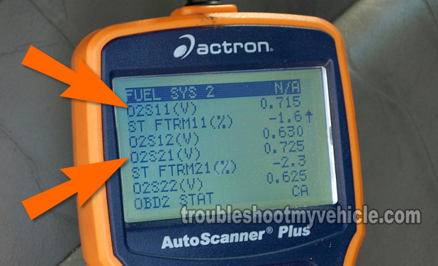
Start your Pathfinder's engine, scroll down to the left and right upstream oxygen sensor PIDs labeled O2S11 and O2S21.
- 2
Make sure your Pathfinder's engine has reached normal operating temperature before you proceed to the next step.
- 3
Have a helper spray a little bit of carburetor cleaner into the intake manifold via a small vacuum hose with the engine running and while you observe the scan tool's upstream oxygen sensor PIDs.
- 4
As soon as the carburetor spray hits the inside of the intake manifold (via the vacuum hose) and enriches the air/fuel mixture, your scan tool should read 0.800 to 1.0 volt for both O2S11 and O2S21.
You can repeat step 3 several times, if you need to make sure of your test result.
Let's take a look at what your test results mean:
CASE 1: The O2S11 and O2S21 values increased to 0.8 to 1 V and stay there as long as you were spraying carb spray. This test result confirms that both the left and right oxygen sensors are OK.
CASE 2: The O2S11 and O2S21 values values did not shoot up as the carb spray was being sprayed. This result confirms that there's a problem with the O2 sensor you're observing on the scan tool or with the multimeter.
Generally, this means that the O2 sensor you're observing/testing is bad and I suggest doing the other two tests (in this tutorial) to make sure. For the first (of two), go to: TEST 3: Checking The Resistance Of The O2 Heater Element.
TEST 3: Checking The Resistance Of The O2 Heater Element

In this test we're going to check the resistance of the heater element within the right (or left) upstream oxygen sensor.
You don't have to remove the right (or left) upstream O2 sensor from your Nissan Pathfinder to test the resistance of a heater element since its connector is easily accessible from the engine compartment.
Since the Nissan factory resistance specifications (for the heater element) calls for the right (or left) upstream sensor to be at room temperature (77 °F (25 °C)), you're going to have to perform this test with a completely cold engine.
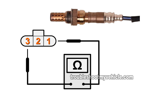
NOTE: The illustration in the image above applies to both the left and right upstream oxygen sensors on your Nissan Pathfinder.
These are the test steps:
- 1
With the key in the OFF position, disconnect the oxygen sensor that you're gonna' test.
NOTE: The engine (and thus the O2 sensor) has to be completely at room temperature. - 2
Measure the resistance between terminals 1 and 3 of the upstream oxygen sensor you're testing (use the illustration in the image above to identify the correct O2 sensor terminals).
The resistance between these two outer terminals of the upstream oxygen sensor should be between 2.3 to 4.3 Ohms (Ω) at 77 °F (25 °C) if all is OK (with the heater element). - 3
Check for continuity between terminals 1 and 2 and check for continuity between terminals 2 and 3. If the upstream sensor is OK, there should NOT be any continuity between these terminals.
Let's take a look at what your test results mean:
CASE 1: The upstream O2 sensor heater element's resistance is within specification and there's no continuity between terminal 1 and 2 and between terminal 2 and 3. This is the correct and expected test result and tells you that the internal heater element of the upstream oxygen sensor you're testing is OK.
So far you have:
- Confirmed that the right (or left) upstream O2 sensor is stuck producing a continuous voltage in TEST 1.
- Confirmed that the right (or left) upstream O2 sensor does NOT react to a manually induced rich condition TEST 2.
- Confirmed that the heater element of the right (or left) upstream O2 sensor is within specification (in this test).
Your next step is to go to: TEST 4: Checking The Continuity Between The O2 Sensor And PCM.
CASE 2: The upstream O2 sensor heater element's resistance is NOT within specification and/or there's continuity between the other terminals. This test result indicates a problem with the heater element of the upstream oxygen sensor you're testing. Replace the oxygen sensor.


