In this tutorial I am going to show you how to test diagnostic trouble codes P0130 and P0150 on your 3.3L equipped Nissan Pathfinder.
These codes indicate a problem with the front O2 sensors which are the sensors located before the catalytic converter for Bank 1 and Bank 2.
This tutorial applies to the 1997 to 2000 3.3L V6 Nissan Pathfinder.
Contents of this tutorial:
- P0130 And P0150 Diagnostic Essentials.
- Diagnosing Trouble Codes P0130 And P0150.
- Where To Buy Your Nissan Pathfinder's O2 Sensors And Save.
- TEST 1: Checking Upstream Oxygen Sensor Performance.
- TEST 2: Manually Inducing A Rich Condition.
- TEST 3: Checking The Resistance Of The O2 Heater Element.
- TEST 4: Checking The Continuity Between The O2 Sensor And PCM.
- More Nissan Pathfinder Test Tutorials.
ES  You can find this tutorial in Spanish here: Cómo Probar Los Códigos P0130 y P0150 (1996-2000 3.3L Nissan Pathfinder) (at: autotecnico-online.com).
P0130 And P0150 Diagnostic Essentials
Usually what causes these two codes to pop up on your Nissan Pathfinder is a failed right (or left) upstream oxygen sensor but not always.
Thankfully, by doing some specific tests, you and I can check to see if they're bad (or not) before replacing them.
Before we jump into the tests, here's some specific information about these two codes that will help us understand exactly what they're trying to tell us:
P0130: O2 Sensor Circuit Malfunction (Bank 1 Sensor 1). This trouble code lets us know that the PCM is detecting that:
- The front O2 sensor for Bank 1 is not switching between 0.2 to 0.8 Volts (as the engine is running).
- That the front O2 sensor for Bank 1 is stuck producing an output voltage of 0.2 - 0.4 Volts DC.
- That the fault could lie in the front oxygen sensor itself or in the wiring between the sensor and the fuel injection computer.
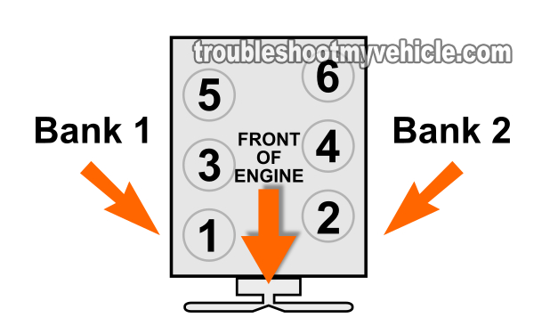
- NOTE: Bank 1 is the bank that houses cylinders 1, 3, and 5.
- Bank 1 Sensor 1 is commonly referred to as:
- Right front oxygen sensor.
- Upstream right oxygen sensor.
- Bank 1 Sensor 1.
- O2S11.
P0150: O2 Sensor Circuit Malfunction (Bank 2 Sensor 1):
- The front O2 sensor for Bank 2 is not switching between 0.2 to 0.8 Volts (as the engine is running).
- That the front O2 sensor for bank 2 is stuck producing an output voltage of 0.2 - 0.4 Volts DC.
- That the fault could lie in the front oxygen sensor itself or in the wiring between the sensor and the fuel injection computer.
- NOTE: Bank 2 is the bank that houses cylinders 2, 4, and 6.
- Bank 2 Sensor 1 is commonly referred to as:
- Left front oxygen sensor.
- Upstream left oxygen sensor.
- Bank 2 Sensor 1.
- O2S21.
As you can see from the information above both codes (P0130 and P0150) aren't accusing either of the two upstream oxygen sensors as having failed since quite a few things can cause them to stay stuck producing a fixed voltage between 0.2 - 0.4 Volts.
Diagnosing Trouble Codes P0130 And P0150
Getting to the bottom of what's causing these 2 codes to light up the check engine light (CEL) on your Nissan Pathfinder involves 4 specific tests.
NOTE: Both the right and left upstream oxygen sensors are tested in the exact same way so all of the tests (in this tutorial) apply to them both.
- The first test is to confirm that the oxygen sensor's output isn't the right output.
- The second test involves creating a rich air fuel mixture and seeing if the right and left upstream O2 sensors react to it.
- The third test involves measuring the resistance of the internal heater of the upstream oxygen sensor.
- The last test involves testing the continuity of the oxygen sensor's wires between its harness connector and the fuel injection computer's harness connector.
Where To Buy Your Nissan Pathfinder's O2 Sensors And Save
If you walk into your local auto parts store you'll notice that the upstream O2 sensors for Bank 1 (right) and Bank 2 (left) are expensive. If you do need to buy new O2 sensors, check out the links below and save:
Right Upstream -Direct Fit:

Left Upstream -Direct Fit:


Disclosure: As an Amazon Associate, I earn from qualifying purchases. If my tutorials help you, using these links is an easy way to support the site at no extra cost to you. Thank you!
TEST 1: Checking Upstream Oxygen Sensor Performance
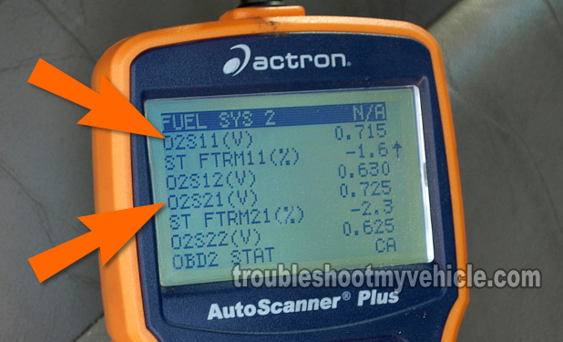
The very first thing that we need to do is check the right (or left) O2 sensor output voltage to see if it's stuck between 0.2 to 0.4 Volts DC after the engine has started and warmed up.
This can be very easily accomplished using a scan tool with live data mode.
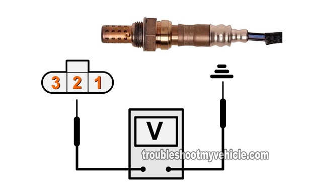
If you don't have a scan tool don't panic because you can use a multimeter to test for the right (or left) upstream oxygen sensor's output voltage (and I'll also include how to do it).
Is you don't have a scan tool and are thinking about buying one or need to upgrade your code reader, check out my recommendation here: ANCEL AD530 OBD2 Scanner w/ Live Data (Amazon affiliate link).
These are the test steps:
- 1
Connect your scan tool, turn the key to the ON position, and go to its live data mode.
If you're using a multimeter: Place the multimeter in Volts DC mode, connect the red lead to the wire to the middle wire of the upstream oxygen sensor you're testing, and Ground the black test lead on the battery negative (-) terminal. - 2
Start your Pathfinder's engine and let it warm up.
In the meantime, scroll down to the PID labeled: O2S11 and O2S21 (see the image in the image viewer).
PID O2S11 represents the output from the right upstream oxygen sensor and PID O2S21 represents the left upstream oxygen sensor. - 3
Once the engine has reached normal operating temperature, PID O2S11 and O2S21 should show a constant sweeping voltage signal of 0.2 to 0.8 Volts.
In other words: The voltage should move constantly between 0.2 Volts to 0.8 Volts the entire time the engine is running.
If you're using a multimeter: Your multimeter should register a voltage (for the upstream O2 sensor you're testing) that's constantly moving between 0.2 Volts to 0.8 Volts as the engine runs.
Let's take a look at what your test results mean:
CASE 1: The upstream oxygen sensor output voltage constantly moved between 0.2 to 0.8 Volts. This test results tells you that the oxygen sensor that you're observing either on your scan tool or with your multimeter is functioning correctly at this point in time.
This test result also tells you that the problem is intermittent since it's not present at this time.
CASE 2: The upstream oxygen sensor output voltage stayed stuck between 0.2 to 0.4 Volts. This test result definitely tells you that the upstream O2 sensor you're observing on your scan tool or multimeter has a problem.
The next step is to manually induce a rich condition and see if the O2 sensor that you're observing responds to this rich condition. If it doesn't respond to it then we know that it has failed and needs to be replaced. For this test go to: TEST 2: Manually Inducing A Rich Condition.
TEST 2: Manually Inducing A Rich Condition
You've reached this point because in TEST 1 you confirmed that the right (or left) upstream oxygen sensor is stuck producing a continuous voltage (when it should be alternating between 0.2 and 0.8 Volts).
The next step is to manually induce a rich condition by spraying carburetor spray into a vacuum hose while the engine runs.
If the right (or left) upstream oxygen sensor on your Nissan Pathfinder is working correctly then as soon as the carb. Spray gets burned in the cylinder you'll see its output voltage should hit 0.8 to 1.0 Volts DC.
IMPORTANT: Take all necessary safety precautions since this test requires that you work around a running engine. Stay alert, use common sense, and be careful.
Here are the step-by-step instructions:
- 1
Start your Pathfinder's engine, scroll down to the left and right upstream oxygen sensor PIDs labeled O2S11 and O2S21.
- 2
Make sure your Pathfinder's engine has reached normal operating temperature before you proceed to the next step.
- 3
Have a helper spray a little bit of carburetor cleaner into the intake manifold via a small vacuum hose with the engine running and while you observe the scan tool's upstream oxygen sensor PIDs.
- 4
As soon as the carburetor spray hits the inside of the intake manifold (via the vacuum hose) and enriches the air/fuel mixture, your scan tool should read 0.800 to 1.0 Volts for both O2S11 and O2S21.
You can repeat step 3 several times, if you need to make sure of your test result.
Let's take a look at what your test results mean:
CASE 1: The O2S11 and O2S21 values increased to 0.8 to 1 V and stay there as long as you were spraying carb spray. This test result confirms that both the left and right oxygen sensors are OK.
CASE 2: The O2S11 and O2S21 values values did not shoot up as the carb spray was being sprayed. This result confirms that there's a problem with the O2 sensor you're observing on the scan tool or with the multimeter.
Generally, this means that the O2 sensor you're observing/testing is bad and I suggest doing the other two tests (in this tutorial) to make sure. For the first (of two), go to: TEST 3: Checking The Resistance Of The O2 Heater Element.
TEST 3: Checking The Resistance Of The O2 Heater Element
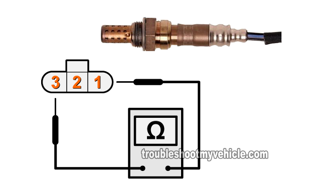
In this test, we're going to check the resistance of the heater element within the right (or left) upstream oxygen sensor.
You don't have to remove the right (or left) upstream O2 sensor from your Nissan Pathfinder to test the resistance of a heater element since its connector is easily accessible from the engine compartment.
Since the Nissan factory resistance specifications (for the heater element) calls for the right (or left) upstream sensor to be at room temperature (77 °F (25 °C)), you're going to have to perform this test with a completely cold engine.
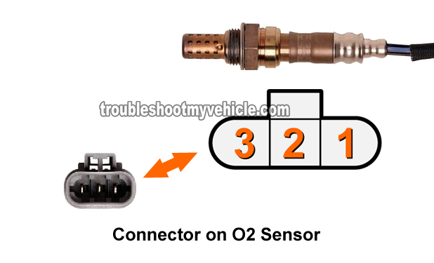
NOTE: The illustration in the image above applies to both the left and right upstream oxygen sensors on your Nissan Pathfinder.
These are the test steps:
- 1
With the key in the OFF position, disconnect the oxygen sensor that you're gonna' test.
NOTE: The engine (and thus the O2 sensor) has to be completely at room temperature. - 2
Measure the resistance between terminals 1 and 3 of the upstream oxygen sensor you're testing (use the illustration in the image above to identify the correct O2 sensor terminals).
The resistance between these two outer terminals of the upstream oxygen sensor should be between 2.3 to 4.3 Ohms (Ω) at 77 °F (25 °C) if all is OK (with the heater element). - 3
Check for continuity between terminals 1 and 2 and check for continuity between terminals 2 and 3. If the upstream sensor is OK, there should NOT be any continuity between these terminals.
Let's take a look at what your test results mean:
CASE 1: The upstream O2 sensor heater element's resistance is within specification and there's no continuity between terminal 1 and 2 and between terminal 2 and 3. This is the correct and expected test result and tells you that the internal heater element of the upstream oxygen sensor you're testing is OK.
So far you have:
- Confirmed that the right (or left) upstream O2 sensor is stuck producing a continuous voltage in TEST 1.
- Confirmed that the right (or left) upstream O2 sensor does NOT react to a manually induced rich condition TEST 2.
- Confirmed that the heater element of the right (or left) upstream O2 sensor is within specification (in this test).
Your next step is to go to: TEST 4: Checking The Continuity Between The O2 Sensor And PCM.
CASE 2: The upstream O2 sensor heater element's resistance is NOT within specification and/or there's continuity between the other terminals. This test result indicates a problem with the heater element of the upstream oxygen sensor you're testing. Replace the oxygen sensor.
TEST 4: Checking The Continuity Between The O2 Sensor And PCM
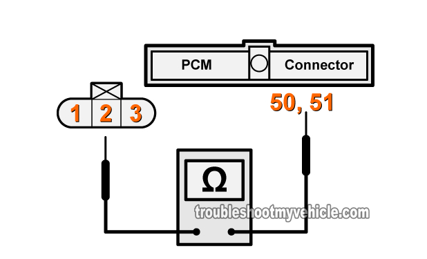
The last battery of tests is to make sure that the wire that connects to terminal number 2 of the right (or left) upstream oxygen sensor isn't shorted to Ground or has an open-circuit problem somewhere between the sensor's harness connector and the PCM's connector.
This can easily be accomplished by doing a continuity test between the right (or left) upstream O2 sensor engine harness connector and the PCM harness connector and a continuity test between terminal number 2 and Ground.
NOTE: The left upstream oxygen sensor terminal number 2 wire connects to pin number 51 of the PCM connector. The right upstream oxygen sensor terminal number 2 wire connects to pin number 50 of the PCM connector.
These are the step tests:
- 1
Disconnect the battery negative (-) terminal and:
Disconnect the upstream oxygen sensor (that you need to test) from its engine harness connector.
Disconnect the PCM from its harness connector. - 2
Testing the right upstream O2 sensor, test continuity between:
Terminal number 2 of the O2's engine harness connector and terminal 50 of the PCM's harness connector.
Continuity should exist. - 3
Testing the left upstream O2 sensor, test continuity between:
Terminal number 2 of the O2's engine harness connector and terminal 51 of the PCM's harness connector.
Continuity should exist. - 4
Test the continuity between:
Terminal number 2 and engine Ground.
Continuity should NOT exist.
NOTE: This test applies to both the right or left upstream oxygen sensor.
Let's take a look at what your test results mean:
CASE 1: All of the continuity tests showed no problems. This test result tells you that that are no ‘opens’ or shorts to Ground in the circuit between the PCM's harness and the O2 sensor' harness connector.
Since you've reached this point because you have:
- Confirmed that the right (or left) upstream O2 sensor is stuck producing a continuous voltage in TEST 1.
- Confirmed that the right (or left) upstream O2 sensor does NOT react to a manually induced rich condition TEST 2.
- Confirmed that the heater element of the right (or left) upstream O2 sensor is within specification in TEST 3.
Tanking these test results into account, you can correctly assume that the upstream O2 sensor you're testing is fried and needs to be replaced with a new one.
CASE 2: One or several of the continuity tests showed a problem. Check all of your connections and repeat a test one more time.
If the continuity tests confirm the problem then repair the short to Ground or the open-circuit problem in the circuit. Repairing this issue will solve the right or left upstream O2 sensor diagnostic trouble code (P0130 or P0150) lighting up the check engine light on your Nissan Pathfinder.
More Nissan Pathfinder Test Tutorials
You can find a complete list of tutorials here: Nissan 3.3L Index Of Articles.
Below is a small sample of the tutorials you'll find in the index:
- How To Test The Idle Switch (Nissan 3.3L Pathfinder, Xterra, Frontier).
- Throttle Position Sensor Test (Nissan 3.3L Pathfinder, Xterra, Frontier).
- How To Troubleshoot A No Start (Nissan 3.0L, 3.3L, 3.5L).
- How To Test The Starter Motor (Nissan 3.0L, 3.3L).
- How To Test Engine Compression (Nissan 3.0L, 3.3L, 3.5L).

If this info saved the day, buy me a beer!