
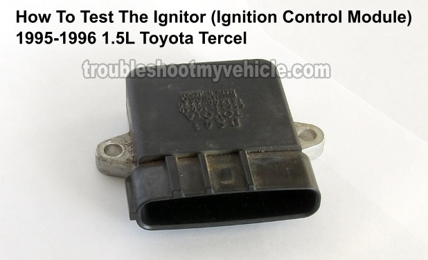
This tutorial will help you test the igniter (ignition control module) on the 1995 thru' 1996 1.5L Toyota Tercel.
You don't need any expensive diagnostic tools to follow the test instructions, since I'll be showing you how to test it using a simple LED light.
I've also included the Oscilloscope wave form patterns for the IGT control signals you'll need to see if you're using one.
Contents of this tutorial:
- Symptoms Of A Bad Igniter.
- Igniter Circuit Descriptions.
- Where To Buy The Igniter (Ignition Control Module).
- Basic Operation Theory Of The Igniter.
- TEST 1: Testing For Spark At All 4 Cylinders.
- TEST 2: Making Sure The Igniter Is Getting Power.
- TEST 3: Making Sure The Igniter Is Getting Ground.
- TEST 4: Testing The Igniter Control Signals.
- TEST 5: Testing The Ignition Coil Control Signals.
ES  You can find this tutorial in Spanish here: Cómo Probar El Módulo De Encendido (1995-1996 1.5L Toyota Tercel) (at: autotecnico-online.com).
WIRING DIAGRAM: You can find the igniter wiring diagram here: Igniter Wiring Diagram 1995-1996 1.5L Toyota Tercel.
You can find the 1997-1998 Toyota Tercel igniter tests here:
Symptoms Of A Bad Igniter
The igniter (which is another name for the ignition control module) is the component that activates the ignition coils sitting on top of the engine's valve cover. When this bad boy fails, your Toyota Tercel is not gonna' start due to a lack of spark (at all four cylinders).
What gives away the igniter as defective, when testing it, is the fact that it's getting battery power, Ground, and its two igniter control signals from the fuel injection computer but it does not activate the ignition coils to fire spark away.
Igniter Circuit Descriptions
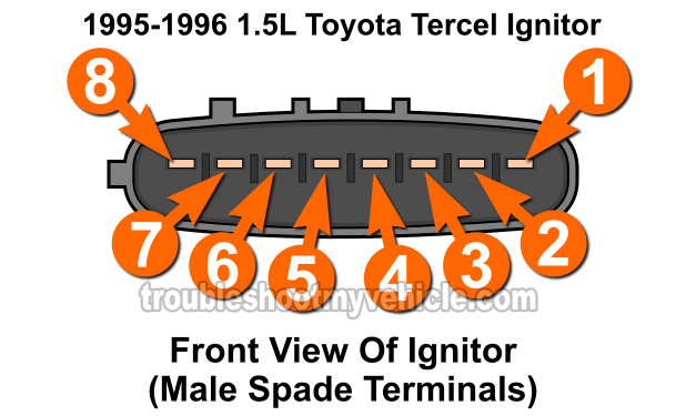
The igniter (ignition control module) has 8 wires coming out of its connector. Each one has a specific job to do and here's a brief description of each:
| 1995-1996 1.5L Tercel Igniter Connector | ||
|---|---|---|
| Pin | Wire Color | Description |
| 1 | Red with white stripe | IGC2 -2/3 Ignition coil control signal |
| 2 | Light green with black stripe | IGF -Ignition coil firing feedback |
| 3 | White with black stripe | GND -Chassis Ground |
| 4 | Blue with yellow stripe | IGT2 -Igniter control signal cylinders 2/3 |
| 5 | Light green | IGT1 -Igniter control signal cylinders 1/4 |
| 6 | Black with blue stripe | TACH -Tachometer signal |
| 7 | Black with orange stripe | +B -Battery power |
| 8 | Red | IGC1 -1/4 Ignition coil control signal |
NOTE: The igniter harness connector has female metal terminals. You'll need to use a back probe or a wiring piercing probe to test the signals in the wires.
Where To Buy The Igniter (Ignition Control Module)
Yup, this bad boy is very expensive. Check out the following links and comparison shop:


Disclosure: As an Amazon Associate, I earn from qualifying purchases. If my tutorials help you, using these links is an easy way to support the site at no extra cost to you. Thank you!
Basic Operation Theory Of The Igniter
In a nutshell, when you turn the key and crank the engine:
- The igniter gets battery power on the igniter harness connector terminal #7 (see illustration above).
- The wire that feeds battery power to the igniter is the black with orange stripe (BLK/ORG) wire.
- This same circuit also feeds battery power to the ignition coils.
- The crankshaft and camshaft position sensors start to generate their signals. These signals are transmitted directly to the fuel injection computer.
- Once the fuel injection computer gets the crank and cam position signals, it sends two igniter (IGT) control signals to the igniter. The IGT signals are what tell the igniter to start activating the ignition coils.
- The signal to activate the 1/4 ignition coil is received on terminal #5. The color of the wire is light green (LT GRN). This circuit is labeled as IGT1
- The signal to activate the 2/3 ignition coil is received on terminal #4. The color of the wire is blue w/ yellow stripe (BLU/YEL). This circuit is labeled as IGT2
- When the igniter receives the igniter control signals, it now activates the ignition coils by switching the ignition coils' primary circuits ON and OFF:
- Ignition coil for cylinders 1/4 is activated thru' the red (RED) wire. This circuit is known as the IGC1 circuit.
- Ignition coil for cylinders 2/3 is activated thru' the red with white stripe (RED/WHT) wire. This circuit is known as the IGC2 circuit.
- Once the ignition coils get their IGC1 and IGC2 signals, they start to spark away.
TEST 1: Testing For Spark At All 4 Cylinders
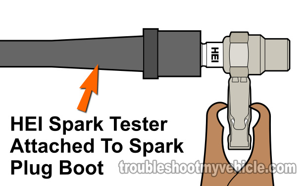
The very first thing we're gonna' do is make sure that spark is missing from all 4 cylinders. If spark is present in all four cylinders (even if your Tercel doesn't start), then you can rule out the igniter as bad.
To get an accurate result, I recommend that you use a dedicated spark tester for this test. If you can, I suggest using an HEI spark tester. You can find out more about it (and where to buy it here: OTC 6589 Electronic Ignition Spark Tester (Amazon affiliate link).
Alright, let's get started:
- 1
Connect your spark tester to spark plug wire for cylinder #1. Ground the spark tester using a battery jump start cable to the battery negative (-) post.
- 2
Have a helper crank the engine while observe the spark tester from a safe distance.
- 3
The spark tester should spark when the engine is cranking.
- 4
Repeat the above 3 steps on the remaining cylinders.
Let's take a look at what your test results mean:
CASE 1: All 4 cylinders have spark. This test result tells you that the igniter is activating the ignition coils and that it's not defective.
CASE 2: No spark on all 4 cylinders. The next step is to make sure that the igniter (and the ignition coils) are getting battery power. For this test go to: TEST 2: Making Sure The Igniter Is Getting Power.
CASE 3: No spark on cylinders 1 and 4. This test result usually tells you that the ignition coil that feeds cylinders 1 and 4 is defective.
CASE 4: No spark on cylinders 2 and 3. This test result usually tells you that the ignition coil that feeds cylinders 2 and 3 is defective.
TEST 2: Making Sure The Igniter Is Getting Power
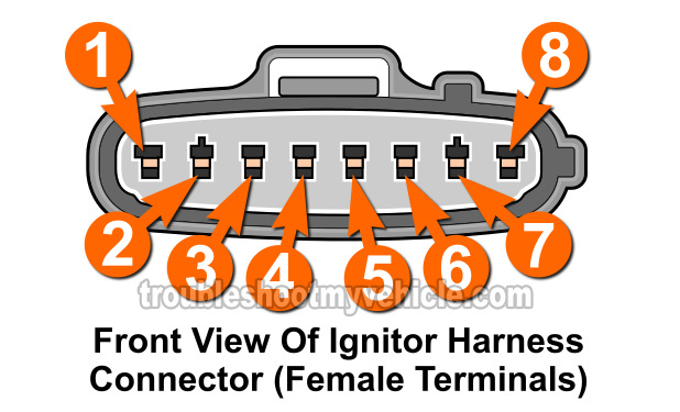
Now that you have confirmed that all 4 cylinders don't have spark, the next step is to make sure that the igniter and ignition coils are getting battery power when the ignition key is turned on.
Since the same circuit feeds the ignition coils and igniter with battery power, we need only test the black with orange stripe (BLK/ORG) of the igniter harness connector for 12 Volts DC.
The BLK/ORG wire connects to terminal #7 of the igniter's electrical connector (see illustration above).
Let's get started:
- 1
Disconnect the igniter from its 8-wire electrical connector.
- 2
Place your multimeter in Volts DC mode.
- 3
Connect the red multimeter test lead to the BLK/ORG wire of the igniter's electrical connector.
This is the wire that connects to terminal number 7 in the illustration above (of the igniter's harness connector). - 4
Connect the black multimeter test lead to the battery negative (-) terminal.
- 5
Have your helper turn the key to the ON position.
- 6
Your multimeter should read 10 to 12 Volts DC if the igniter and ignition coils are getting battery power.
Let's take a look at what your test results mean:
CASE 1: The igniter is getting 10 to 12 Volts DC. This is the correct and expected test result. The next step is to make sure the igniter is getting Ground. For this step, go to: TEST 3: Making Sure The Igniter Is Getting Ground.
CASE 2: The igniter IS NOT getting battery power. This tells you that the igniter is not working due to a lack of battery power.
Your next step is to find out why this battery power is missing and restore it. Once battery power is restored, the igniter should function again.
TEST 3: Making Sure The Igniter Is Getting Ground
So far, you made sure that:
- All four cylinders are not getting spark.
- The igniter is getting power.
In this test step, we're gonna' make sure that the igniter (ignition module) is getting Ground.
Ground is fed to the igniter by the black with white stripe (BLK/WHT) wire of the number 3 terminal of the harness connector.
Let's get started:
- 1
Disconnect the igniter from its 8-wire electrical connector.
- 2
Place your multimeter in Volts DC mode.
- 3
Connect the black multimeter test lead to the WHT/BLK wire of the igniter's electrical connector.
This is the wire that connects to terminal number 3 in the illustration above (of the igniter's harness connector). - 4
Connect the red multimeter test lead to the battery positive (+) terminal.
- 5
Your multimeter should read 10 to 12 Volts DC with the Key On and Off (if Ground is present).
Let's take a look at what your test results mean:
CASE 1: The igniter is getting Ground. This is the correct and expected test result.
The next step is to make sure the igniter is getting the IGT signals from the fuel injection computer. For this step, go to: TEST 4: Testing The Igniter Control Signals.
CASE 2: The igniter IS NOT getting Ground. This tells you that the igniter is not working due to a lack of chassis Ground.
Your next step is to find out why this Ground is missing and restore it. Once Ground is restored, the igniter should function again.
TEST 4: Testing The Igniter Control Signals
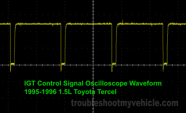
So far, you made sure that:
- All four cylinders are not getting spark.
- The igniter is getting battery power and Ground.
In this test step, we're gonna' use an LED light to see if the igniter (ignition module) is getting the IGT1 and IGT2 control signals from the fuel injection computer.
The IGT1 signal is fed to the igniter by the light green (LT GRN) wire of the number 5 terminal of the harness connector. The IGT1 signal is the one that tells the igniter to activate the ignition coil for cylinders #1 and #4.
The IGT2 signal is fed to the igniter by the blue with yellow stripe (BLU/YEL) wire of the number 4 terminal of the harness connector. The IGT2 signal is the one that tells the igniter to activate the ignition coil for cylinders #2 and #3.
IMPORTANT: You'll need to use an automotive LED light with a built in resistor. A 12 Volt test light will not work and can damage the igniter. You can see an example of this LED (with built in resistor) here: Oznium Flush Mount 12V LED Light (Amazon affiliate link).
IMPORTANT: The igniter must remain connected to its electrical connector for this test to function. To access the IGT signals inside the wire, you'll need to use either a back probe or a wiring piercing probe. You can see an example of a wiring piercing probe here: Goupchn 4mm Banana to Banana Plug Test Leads Kit (Amazon affiliate link).
These are the test steps:
- 1
Connect the red LED wire to the LT GRN wire of the igniter's electrical connector. This is the wire that connects to terminal number 5 in the illustration above (of the igniter's harness connector).
NOTE: The igniter must remain connected to its electrical connector. - 2
Connect the black LED wire to the battery negative (-) terminal.
- 3
After the LED light is set up, have your helper crank the engine as you observe the LED light.
- 4
The LED light should flash ON and OFF in steady pulses as the engine is cranking if the IGT1 signal is present.
- 5
Repeat steps 1 thru' 4 on the BLU/YEL wire to test for the IGT2.
Let's take a look at what your test results mean:
CASE 1: The LED light flashed on both circuits (wires) tested. This is the correct and expected test result and tells you that the igniter is getting the IGT1 and IGT2 control signals from the fuel injection computer.
The next step is to make sure that the igniter is now creating the activation signal for the 1/4 ignition coil and the 2/3 ignition coil. For this step, go to: TEST 5: Testing The Ignition Coil Control Signals.
CASE 2: The LED light DID NOT flash on both circuits (wires) tested. This tells you that the igniter is not activating the ignition coils due to a lack of the IGT control signals.
The most common reason the IGT1 and IGT2 signals are missing is a defective crankshaft position sensor. Although it's beyond the scope of this tutorial to test the crankshaft position (CKP) sensor, your next step is to test it:
TEST 5: Testing The Ignition Coil Control Signals
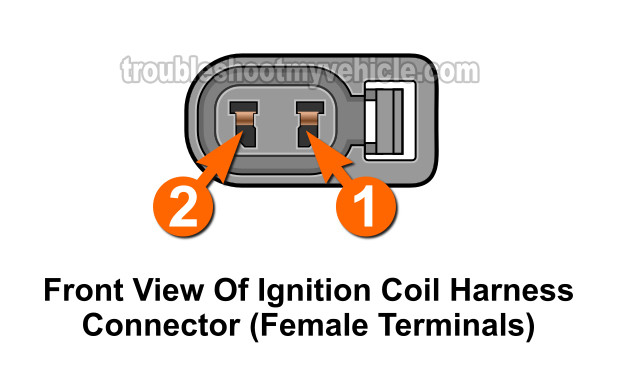
You've reached this last test because you have tested and confirmed that:
- All four cylinders are not getting spark (TEST 1).
- The igniter is getting battery power and Ground (TEST 2 and 3).
- The igniter is getting both the IGT1 and IGT2 signals (TEST 4).
Since the igniter is receiving all these, it should create two separate ignition coil control signals (IGC1 and IGC2).
So in this last test step, we're gonna' use an LED light to see if the igniter (ignition module) is creating the IGC1 and IGC2 control signals that the ignition coils need to start sparking.
We'll check for these signals directly at the ignition coil connectors
NOTE: The IGC1 signal is the one that activates the 1/4 ignition coil and the IGC2 signal is the one that activates the 2/3 ignition coil.
IMPORTANT: The igniter must remain connected to its electrical connector for this test to function.
These are the test steps:
- 1
Disconnect 1/4 (or 2/3) ignition coil from its electrical connector.
- 2
Connect the red LED wire to terminal #1 of the ignition coil harness connector (see illustration above). The wire that connects to the #1 terminal is a black with orange stripe (BLK/ORG) wire.
CAUTION: You'll connect the LED wire to the female terminal of the connector. Do not insert a large diameter test lead into the female terminal of the ignition coil connector or you'll damage the female terminal! - 3
Connect the black LED wire to the #2 terminal of the ignition coil harness connector (see illustration above). The wire connecting to the #2 terminal should be a red (RED) wire.
- 4
After the LED light is set up, have your helper crank the engine as you observe the LED light.
- 5
The LED light should flash ON and OFF in steady pulses as the engine is cranking if the IGC signal is present (for this ignition coil being tested).
- 6
Repeat steps 1 thru' 5 on the 2/3 ignition coil harness connector to test for the IGC2 signal.
NOTE: On 2/3 ignition coil connector, terminal #2 has a red with white stripe (RED/WHT) wire and terminal #1 is the same color (BLK/ORG).
Let's take a look at what your test results mean:
CASE 1: The LED light flashed on both ignition coil connectors. This is the correct and expected test result and tells you that the igniter is creating and sending the IGC1 and IGC2 control signals to the ignition coils.
This test result tells you that the igniter (ignition control module) is functioning correctly and that the 'no spark, no-start' condition is due to another cause.
CASE 2: The LED light DID NOT flash on both ignition coil connectors. This tells you that the igniter is not activating the ignition coils.
You can now conclude that the igniter is defective only if you have tested and confirmed that:
- All four cylinders are not getting spark (TEST 1).
- The igniter is getting battery power and Ground (TEST 2 and 3).
- The igniter is getting both the IGT1 and IGT2 signals (TEST 4).
- The igniter is not creating/sending the IGC1 and IGC2 signals to the ignition coils (TEST 5).

If this info saved the day, buy me a beer!
