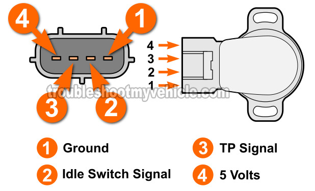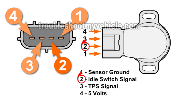
Testing the idle switch part of the throttle position sensor (TPS) on the 1995-1996 1.5L Toyota Tercel isn't difficult.
In this tutorial, I'm going to show you how to do it in a step-by-step way.
You'll be able to easily find out if it's out of adjustment or not. If it is out of adjustment, then you'll be able to easily adjust it to specification.
NOTE: This tutorial applies to the 1995-1996 1.5L Toyota Tercel.
Contents of this tutorial:
TPS TEST: If you need to test the throttle position sensor part of the idle switch, this tutorial will help: How To Test The Throttle Position Sensor (1995-1996 1.5L Toyota Tercel).
Idle Switch Continuity Tests

To find out if the idle switch is adjusted to its specification, we're going to test the continuity between two specific terminals (of the switch) with our multimeter in Ohms mode.
The two TPS terminals that we need to locate/identify are terminal #2 and terminal #1 (using the illustration above).
1. Turn off the ignition switch and disconnect the TPS from its engine wiring harness connector.
2. Insert the specified thickness feeler gauge between the throttle stop screw and throttle lever and check for the specific continuity shown in the table below (to see the location of where you need to place the feeler gauge: Location Of The Throttle Stop Screw). If not within specification, adjust or replace the TPS assembly.
| Idle Switch Continuity Specifications | ||
|---|---|---|
| Feeler Gauge Thick. | Pins | Ohms |
| .020 In. (.51 mm) | 1 and 2 | Continuity |
| .028 In. (.71 mm) | 1 and 2 | No-continuity |
If the throttle switch on your 1.5L Toyota Tercel doesn't show continuity with a .020 In. feeler gauge between the idle stop screw and the throttle lever, then before replacing it, you need to make sure that it's not misadjusted. The next subheading will help you with this procedure.
Adjusting The Throttle Position Sensor Assembly

The idle switch adjustment is a pretty easy thing and in this section I'll show you how to do it.
This is what you'll need to do:
- Turn the ignition switch to its Off position and make sure the TP sensor assembly is disconnected from its connector.
- Place your multimeter in Ohms mode.
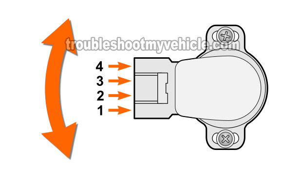
- Loosen the screws that hold the TPS to the throttle body.
- Place a .024 In. (.61 mm) feeler gauge between the throttle stop screw and the throttle lever and:
- Test continuity between terminal #1 and #2. Your multimeter should register CONTINUITY.
- If contintuity exists, between terminal #1 and #2, then tighten the TPS screws and go to step 4.
- If continuity DOES NOT exists, adjust the TPS sensor by rotating it until CONTINUITY exists and tighten the TPS screws. When done go to step 4.
- Place a .020 In. (.51 mm) feeler gauge between the throttle stop screw and the throttle lever and:
- Test continuity between terminal #1 and #2. Your multimeter should register continuity.
- If continuity does not exist, go back to step 3.
- Once you're done, recheck the continuity between terminals #1 and #2 to make sure the adjustment is within specification.
