
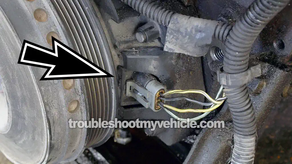
The crankshaft position (CKP) sensor on the 1994-2005 3.8L V6 Buick LeSabre can be tested with nothing more than a multimeter. In this tutorial, I'll show you exactly how to do it and walk you through the entire testing process step by step.
Now, if you're wondering whether you can test this crankshaft position sensor with a simple resistance (Ohms) test, the answer is no. The 3X/18X CKP sensor is a Hall-effect sensor, and Hall-effect sensors can't be tested by measuring their internal resistance with a multimeter.
Instead, they have to be tested while they're working. The cool thing is that you don't need a scan tool or any expensive test equipment to do it. I'll show you one of the most effective ways to test the 3X/18X CKP sensor using only a multimeter set to Volts DC.
Contents of this tutorial:
- Symptoms Of A Bad CKP Sensor.
- Where To Buy The CKP Sensor And Save.
- How The CKP Sensor Works.
- TEST 1: Testing The 3X Sync Signal.
- TEST 2: Testing The 18X Signal.
- TEST 3: Making Sure The CKP Sensor Is Getting Power.
- TEST 4: Making Sure The CKP Sensor Is Getting Ground.
- More 3.8L Buick LeSabre Diagnostic Tutorials.
NOTE: This tutorial applies to the following vehicles:
- 3.8L V6 Buick LeSabre: 1994, 1995, 1996, 1997, 1998, 1999, 2000, 2001, 2002, 2003, 2004, 2005.
CKP SENSOR CIRCUIT WIRING DIAGRAMS:
- ICM And CKP/CMP Sensor Circuit Wiring Diagram (1994-1995 3.8L V6 Buick LeSabre).
- ICM And CKP/CMP Sensor Circuit Wiring Diagram (1996-1997 3.8L V6 Buick LeSabre).
- ICM And CKP/CMP Sensor Circuit Wiring Diagram (1998-2000 3.8L V6 Buick LeSabre).
- ICM And CKP/CMP Sensor Circuit Wiring Diagram (2001-2002 3.8L V6 Buick LeSabre).
- ICM And CKP/CMP Sensor Circuit Wiring Diagram (2003-2005 3.8L V6 Buick LeSabre).
CMP SENSOR TESTS: How To Test The CMP Sensor -P0341 (1994-2005 3.8L V6 Buick LeSabre).
Symptoms Of A Bad CKP Sensor
The most common symptom of a failed crankshaft position (CKP) sensor is an engine that cranks normally but won't start. In other words, the starter motor turns the engine over, but the engine never fires up.
When the CKP sensor fails, you'll usually notice one or more of the following symptoms:
- The ignition system won't produce spark:
- No spark from any of the ignition coil pack towers.
- No spark from any of the six spark plug wires.
- The fuel injectors won't pulse: Without the CKP sensor signals, the PCM won't trigger the fuel injectors.
- On 1996-2005 OBD II models, the PCM may store one or both of the following trouble codes:
- P0336: 18X Reference Signal.
- P1374: 3X Reference Signal.
The thing to keep in mind is this: if you're getting spark from any spark plug wire or ignition coil tower while cranking the engine, then the crankshaft position sensor is doing its job. In that case, the tests in this tutorial won't help you because the no-start problem is being caused by something else.
Where To Buy The CKP Sensor And Save
You can buy a replacement crankshaft position sensor at most auto parts stores, but you'll usually find the best prices by shopping online.
The following links let you comparison shop for an original ACDelco crankshaft position sensor, quality aftermarket replacements for your 1994-2005 3.8L V6 Buick LeSabre:


Disclosure: As an Amazon Associate, I earn from qualifying purchases. If my tutorials help you, using these links is an easy way to support the site at no extra cost to you. Thank you!
How The CKP Sensor Works
The crankshaft position (CKP) sensor used on the 1994-2005 3.8L V6 engine is commonly referred to as the 3X/18X CKP sensor. The reason for this name is that it's actually two Hall-effect sensors housed in one assembly. One sensor generates three crankshaft position signals for every crankshaft revolution (the 3X signal), while the other generates eighteen signals per revolution (the 18X signal).
Since it's a Hall-effect sensor, it needs both power and Ground to generate these signals. The signals themselves are digital ON/OFF voltage signals that can be checked with a multimeter, an oscilloscope, and even an LED test light.
Here's a basic overview of how the 3X/18X CKP sensor works:
- When you crank the engine:
- The ignition control module (ICM) supplies the CKP sensor with operating voltage and Ground.
- The operating voltage is approximately 10 Volts DC.
- As the crankshaft begins to rotate:
- The interrupter blades attached to the harmonic balancer pass through the CKP sensor.
- One Hall-effect sensor generates three ON/OFF pulses for every crankshaft revolution (the 3X signal).
- The other Hall-effect sensor generates eighteen ON/OFF pulses for every crankshaft revolution (the 18X signal).
- That's why GM service information refers to it as the 3X/18X CKP sensor.
- The ICM receives both signals:
- Using these signals, the ICM begins firing the ignition coil packs.
- The ICM also sends the necessary reference signal to the PCM so it can begin pulsing the fuel injectors and manage the rest of the engine controls.
- If either CKP signal is lost:
- The ignition system won't produce spark.
- The fuel injectors won't pulse.
- The engine will crank normally but won't start.
The thing to keep in mind is that a failed 3X/18X crankshaft position sensor will usually cause a cranks-but-doesn't-start condition because the ignition system loses spark and the fuel injectors stop pulsing.
TEST 1: Testing The 3X Sync Signal
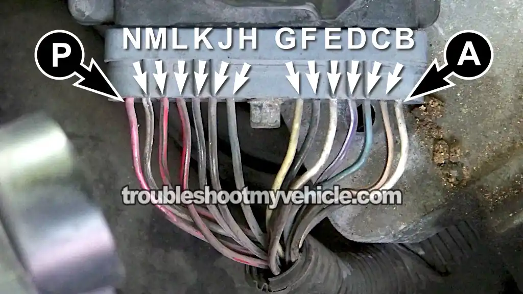
Even though the 3X/18X CKP sensor is mounted behind the harmonic balancer, we're not gonna test it there.
Instead, we're gonna test the 3X signal right at the ignition control module (ICM) connector. The cool thing is that this gives us quick and easy access to the CKP sensor signals without having to work around the harmonic balancer.
CAUTION: This test requires you to manually rotate the engine with the front of the vehicle raised off the Ground. So, it goes without saying (but I'm gonna say it anyway): think safety at all times. Support the vehicle with quality jack stands and never rely on a hydraulic jack alone.
IMPORTANT: The CKP sensor and the ignition control module must remain connected during this test. You'll need to use either a back probe on the connector or a wire-piercing probe on the wire itself. You can see what this tool looks like and where to buy it here: Goupchn 4mm Banana to Banana Plug Test Leads Kit (Amazon affiliate link).
These are the test steps:
PART 1:
- 1
Raise the front of the vehicle and support it securely on jack stands. You'll need enough room underneath the vehicle to comfortably turn the crankshaft by hand.
- 2
Remove the passenger-side front wheel. If the wheel turns while you're trying to loosen the lug nuts, have a helper press the brake pedal to keep the wheel from rotating.
- 3
Remove the plastic splash shield that covers the harmonic balancer and serpentine belt.
- 4
Disable the fuel system by unplugging all six fuel injectors.
This is an important step because it prevents the engine from accidentally starting while you're performing the test. - 5
Locate the ignition control module connector and unplug it.
Remove enough of the wire loom and electrical tape to expose the wires you'll be testing.
IMPORTANT: Once you've exposed the wires, reconnect the connector to the ignition control module. The connector must remain plugged in during the test.
PART 2:
- 6
Set your multimeter to Volts DC mode.
- 7
Connect the red multimeter lead to the wire identified by the letter H in the illustration above.
A back-probe or wire-piercing probe works great for this. - 8
Connect the black multimeter lead to the battery negative (-) terminal.
- 9
Slowly rotate the crankshaft clockwise by hand while watching the multimeter.
Don't use the starter motor for this test. The engine must be turned by hand using a ratchet, extension, and the correct socket on the crankshaft pulley bolt. - 10
Watch the multimeter for an ON/OFF voltage signal.
An ON signal is approximately 5 to 6 Volts DC, and an OFF signal is approximately 0 Volts.
Now let's interpret your test results:
CASE 1: The multimeter registered a switching 5 to 6-Volt ON/OFF signal as you manually turned the engine. This confirms that the CKP sensor is generating a good 3X signal and that the signal is reaching the ignition control module.
Our next step is to verify the 18X CKP signal. Head over to: TEST 2: Testing The 18X Signal.
CASE 2: The multimeter didn't register the 5 to 6-Volt ON/OFF signal. This usually indicates that the CKP sensor isn't generating the 3X signal.
At this point, a lot of folks would replace the crankshaft position sensor, and in most cases that takes care of the problem.
Before condemning the sensor, though, I recommend performing a few more tests. We've still got to verify that the CKP sensor is generating the 18X signal and that it's receiving both power and Ground. Head over to: TEST 2: Testing The 18X Signal.
TEST 2: Testing The 18X Signal
Testing the 18X CKP signal is almost identical to the 3X signal test you just completed.
The only real difference is that the 18X signal switches ON and OFF much faster because it generates eighteen pulses per crankshaft revolution instead of three.
As before, don't use the starter motor to crank the engine. We've got to rotate the crankshaft by hand and continue following all of the necessary safety precautions.
IMPORTANT: The crankshaft position sensor and the ignition control module must remain connected during this test. You'll need to use either a back probe on the connector or a wire-piercing probe on the wire itself. You can see what this tool looks like and where to buy it here: Goupchn 4mm Banana to Banana Plug Test Leads Kit (Amazon affiliate link).
Let's get started:
- 1
Make sure all six fuel injectors are still disconnected.
This prevents the engine from accidentally starting while you're rotating the crankshaft by hand. - 2
Set your multimeter to Volts DC mode.
- 3
Connect the red multimeter lead to the wire identified by the letter G in the illustration above.
This is the circuit that carries the 18X CKP signal from the crankshaft position sensor to the ignition control module.
A back-probe or wire-piercing probe works great for this. - 4
Connect the black multimeter lead to the battery negative (-) terminal.
- 5
Slowly rotate the crankshaft clockwise by hand while watching the multimeter.
Just a friendly reminder: don't use the starter motor for this test. - 6
Watch for a switching ON/OFF voltage signal.
A good 18X signal will switch between approximately 5 to 6 Volts DC (ON) and 0 Volts (OFF).
NOTE: Turn the crankshaft slowly and steadily so the voltage changes are easy to see on the multimeter.
Now let's interpret your test results:
CASE 1: The multimeter registered a switching 5 to 6-Volt ON/OFF signal as you turned the crankshaft by hand. This confirms that the CKP sensor is generating a good 18X signal.
Since you've now verified that both the 3X and 18X CKP signals are being generated and are reaching the ignition control module, you can eliminate the crankshaft position sensor as the cause of the no-start condition.
If your engine still cranks but won't start, then the problem lies somewhere else. The following tutorial will give you additional troubleshooting ideas:
CASE 2: The multimeter didn't register the 5 to 6-Volt ON/OFF signal as you turned the crankshaft by hand. This tells us that the 18X portion of the CKP sensor isn't producing its signal. Now we've got two possible scenarios:
SCENARIO 1: If TEST 1 showed a good 3X signal but this test showed no 18X signal, you can conclude that the crankshaft position sensor is defective and needs to be replaced.
If you need to buy a replacement CKP sensor, take a look at my recommendations here: Where To Buy The CKP Sensor And Save.
SCENARIO 2: If TEST 1 showed no 3X signal and this test also showed no 18X signal, we've still got to verify that the CKP sensor is receiving both power and Ground. If both are present, you can confidently conclude that the crankshaft position sensor is bad. Head over to: TEST 3: Making Sure The CKP Sensor Is Getting Power.
TEST 3: Making Sure The CKP Sensor Is Getting Power
Our next step is to make sure the crankshaft position sensor is receiving its operating voltage from the ignition control module (ICM).
Just like the previous tests, we'll check this circuit right at the ignition control module connector. The ICM supplies the CKP sensor with approximately 10 Volts DC, and we'll use a multimeter to verify that this voltage is present.
IMPORTANT: The ignition control module connector must remain plugged into the ICM during this test. Otherwise, the ICM can't supply power to the crankshaft position sensor. You'll need to use either a back probe on the connector or a wire-piercing probe on the wire itself. You can see what this tool looks like and where to buy it here: Goupchn 4mm Banana to Banana Plug Test Leads Kit (Amazon affiliate link).
OK, let's get'er done:
- 1
Set your multimeter to Volts DC mode.
- 2
Probe the wire identified by the letter N in the illustration above with the red multimeter lead.
NOTE: The ignition control module connector must remain plugged in while you're performing this test. - 3
Connect the black multimeter lead directly to the battery negative (-) terminal.
- 4
Have a helper turn the ignition key to the ON position.
Don't crank the engine. The ICM supplies the CKP sensor with operating voltage as soon as the key is turned to the ON position. - 5
Your multimeter should register approximately 10 Volts DC.
Now let's interpret your test results:
CASE 1: The multimeter registered approximately 10 Volts. This is the correct and expected test result. It confirms that the ignition control module is supplying the crankshaft position sensor with its operating voltage.
Our next step is to make sure the ignition control module is providing the CKP sensor with a good Ground. Head over to: TEST 4: Making Sure The CKP Sensor Is Getting Ground.
CASE 2: The multimeter didn't register approximately 10 Volts. This tells you that the ignition control module isn't supplying power to the crankshaft position sensor.
This also lets you eliminate the CKP sensor as the cause of your cranks-but-doesn't-start condition. Without its operating voltage, the sensor can't generate either the 3X or 18X crankshaft position signals.
TEST 4: Making Sure The CKP Sensor Is Getting Ground
The last thing we've got to verify is that the ignition control module (ICM) is providing the crankshaft position sensor with a good Ground.
Unlike most engine sensors, the 3X/18X CKP sensor gets its Ground directly from the ignition control module. Because of this, you've got to be careful not to accidentally apply battery voltage to this circuit while testing it, or you could damage the ICM.
Just like the previous test, we'll use the multimeter in Volts DC mode to check this circuit.
IMPORTANT: The ignition control module connector must remain plugged into the ICM during this test. Otherwise, the CKP sensor won't have its Ground path. You'll need to use either a back probe on the connector or a wire-piercing probe on the wire itself. You can see what this tool looks like and where to buy it here: Goupchn 4mm Banana to Banana Plug Test Leads Kit (Amazon affiliate link).
Here's what you need to do:
- 1
Set your multimeter to Volts DC mode.
- 2
Probe the wire identified by the letter M in the illustration above with the black multimeter lead.
NOTE: The ICM must remain connected to its connector to check the CKP sensor's Ground. - 3
Connect the red multimeter lead directly to the battery positive (+) terminal.
- 4
Turn the ignition key to the ON position, but don't crank or start the engine.
- 5
Your multimeter should register battery voltage (approximately 10 to 12 Volts DC).
Now let's interpret your test results:
CASE 1: The multimeter registered approximately 10 to 12 Volts. This is the correct and expected test result. It confirms that the ignition control module is providing the crankshaft position sensor with a good Ground path.
You can confidently conclude that the 3X/18X crankshaft position sensor is defective if you've confirmed all of the following:
- TEST 1 and TEST 2: The CKP sensor isn't producing the 3X signal, the 18X signal, or both.
- TEST 3: The ignition control module is supplying the CKP sensor with its operating voltage.
- This test: The ignition control module is providing the CKP sensor with a good Ground.
If you need to replace the crankshaft position sensor, take a look at my recommendations here: Where To Buy The CKP Sensor And Save.
CASE 2: The multimeter didn't register approximately 10 to 12 Volts. This tells you that the ignition control module isn't providing the crankshaft position sensor with a Ground path.
This also lets you eliminate the CKP sensor as the cause of your cranks-but-doesn't-start condition. Without a good Ground, the CKP sensor can't generate either the 3X or 18X crankshaft position signals.
Although it's uncommon for the ignition control module to lose this Ground circuit, it does happen. More often than not, the problem is a poor connection at the ICM connector, such as a female terminal that's backed out of the connector or isn't making good contact with the corresponding terminal on the ignition control module.
More 3.8L Buick LeSabre Diagnostic Tutorials
I have written several other 3.8L V6 specific articles that may be of interest to you, you can find them here:
Here's a sample of the tutorials you'll find in the index:
- Common Causes Of Spark Plug Failure (1994-2005 3.8L V6 Buick LeSabre).
- How To Test The TPS With A Multimeter (1996-2005 3.8L V6 Buick LeSabre).
- How To Test Engine Compression (1994-2005 3.8L V6 Buick LeSabre).
- How To Test For A Blown Head Gasket (1994-2005 3.8L V6 Buick LeSabre).

If this info saved the day, buy me a beer!
