

Got a MAP sensor trouble code (DTC) lighting up the check engine light and your van's engine isn't running quite right? The MAP sensor could very well be the culprit.
That said, the MAP DTC might also stem from a different engine problem —one that has nothing to do with the MAP sensor itself.
The good news? Testing the MAP sensor on your Dodge Ram van is a pretty simple job. You won't need a scan tool —just a standard multimeter and a hand-operated vacuum pump. In this guide, I'll walk you through how to test it step-by-step.
Contents of this tutorial:
- Symptoms Of A Bad MAP Sensor.
- How The MAP Sensor Works.
- Where To Buy The MAP Sensor And Save.
- TEST 1: Verifying The MAP Signal.
- TEST 2: Making Sure That The MAP Sensor Is Getting Power.
- TEST 3: Verifying The MAP Sensor Ground Circuit.
- MAP Sensor Code Won't Go Away.
- More 3.9L V6 Dodge Ram Van Tutorials.
ES  You can find this tutorial in Spanish here: Cómo Probar El Sensor MAP Con Multímetro (1997-2003 3.9L V6 Dodge Ram Van) (at: autotecnico-online.com).
APPLIES TO: This tutorial applies to the following vehicles:
- 3.9L V6 Dodge Ram B1500 Van: 1997, 1998, 1999, 2000, 2001, 2002, 2003.
- 3.9L V6 Dodge Ram B2500 Van: 1997, 1998, 1999, 2000, 2001, 2002, 2003.
OTHER MAP SENSOR TESTS:
- How To Test The MAP Sensor (1989-1990 3.9L V6 Dodge Ram Van).
- How To Test The MAP Sensor (1991 3.9L V6 Dodge Ram Van).
- How To Test The MAP Sensor (1992-1997 3.9L V6 Dodge Ram Van).
Symptoms Of A Bad MAP Sensor
When the MAP sensor goes bad, the fuel injection computer will illuminate the check engine light (CEL) and register one of these two diagnostic trouble codes (DTCs):
- P0107: MAP Sensor Circuit – Voltage Too Low.
- P0108: MAP Sensor Circuit – Voltage Too High.
Besides triggering a MAP-specific code, a faulty sensor may also cause one or more of the following symptoms:
- Rough idle: The engine might idle unevenly or shake when you're stopped in Drive — like when you're waiting at a stoplight.
- Black smoke: A noticeable cloud of black smoke from the exhaust, especially when accelerating, often points to MAP sensor issues.
- Sudden engine stalls: The engine may shut off without warning, either while you're coasting or just starting to accelerate.
- Stalls right after startup: The engine may crank and fire up, only to die immediately afterward.
- Power loss: Acceleration might feel weak or sluggish, making it hard for your van to pick up speed.
- Limp-In Mode: To prevent further damage, the computer may switch into limp mode — which severely limits engine performance and kills fuel economy.
NOTE: Keep in mind that other engine problems (totally unrelated to the MAP sensor) can sometimes cause the computer to log a MAP code. So the smart move is to test the sensor first before jumping to replace it.
In the steps ahead, I'll walk you through a simple bench test to help you confirm whether the MAP sensor is actually at fault. If it passes, you'll know to keep troubleshooting elsewhere.
How The MAP Sensor Works
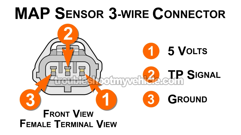
Your Dodge Ram van doesn't use a mass airflow (MAF) sensor to measure how much air is coming in. Instead, it operates using a Speed Density system.
In this type of setup, the fuel injection computer estimates airflow by constantly monitoring input from three key components:
- The manifold absolute pressure (MAP) sensor.
- The intake air temperature (IAT) sensor –which tells the computer how warm or cool the air is.
- Engine RPM –supplied by the crankshaft position (CKP) sensor.
Using this data, the computer figures out how much air is entering the engine and calculates the correct amount of fuel to inject.
Here's a quick overview of what happens when you start the engine:
- Powering the MAP sensor: The computer sends both power and Ground to the MAP sensor to get it up and running:
- 1997 Vans: The violet with white stripe (VIO/WHT) wire supplies 5 Volts DC and connects to terminal 3 (refer to the diagram above).
- 1998+ Vans: The orange (ORG) wire supplies 5 Volts DC and connects to terminal 3.
- The black with light blue stripe (BLK/LT BLU) wire provides the Ground connection and hooks up to terminal 1.
- Reading intake vacuum: The MAP sensor begins measuring the vacuum pressure inside the intake manifold.
- Managing fuel delivery: With information from the MAP, IAT, and CKP sensors, the computer determines the proper air-fuel mix. It then:
- Modifies the injector pulse width, controlling how long each injector remains open.
- Fine-tunes the ignition timing for smoother performance and better fuel efficiency.
Now that you've got a clear picture of how the system works, let's move on to the actual testing steps!
Where To Buy The MAP Sensor And Save
You can pick up a MAP sensor for your Dodge Ram van at just about any local auto parts store —but chances are, you'll end up paying more.
My suggestion? Take a few minutes to browse online or, at the very least, check and compare prices. It's a quick way to see how much you might save. Here are a few options I recommend:


Disclosure: As an Amazon Associate, I earn from qualifying purchases. If my tutorials help you, using these links is an easy way to support the site at no extra cost to you. Thank you!
Not sure if the above MAP sensor fits your particular Dodge Ram van? Don't worry, once you get to the site, they'll make sure it fits by asking you the particulars of your vehicle. If it doesn't fit, they'll find you the right one.
TEST 1: Verifying The MAP Signal

Let's get started! The first thing you'll want to do is see if your MAP sensor generates a changing voltage signal when you manually apply vacuum.
To test this, hook up your multimeter to the MAP sensor's signal wire. Then, apply vacuum using a hand-held vacuum pump —or, if you don't have one, you can draw vacuum by mouth.
Based on the sensor's "health", you'll see one of two results:
- Good Sensor: As you apply and release vacuum, the voltage reading on your multimeter should drop and rise in response.
- Bad Sensor: If the sensor is faulty, the voltage will stay stuck at the same number, no matter how much vacuum you apply.
NOTE: Need a multimeter or a vacuum pump (or thinking about upgrading)? These are the exact ones I personally use and recommend:
- Multimeter: Tekpower TP8268 AC/DC Auto/Manual Range Digital Multimeter (Amazon affiliate link).
- Vacuum pump: HTOMT 2 In 1 Vacuum Pump Test Set (Amazon affiliate link).
Alright, here's how to run the test:
- 1
Remove the MAP sensor from the throttle body.
- 2
Connect your vacuum pump to the MAP sensor's vacuum port.
IMPORTANT: Be sure the sensor remains plugged into its 3-wire connector throughout the test. - 3
Switch your multimeter to DC voltage mode.
- 4
Attach the black lead of your multimeter to the battery's negative (-) post.
- 5
Connect the red multimeter lead to the middle wire of the MAP sensor connector.
The middle wire of the connector should be a dark green with red stripe (DK GRN/RED) wire.
NOTE: You can use a back probe or a wire-piercing tool for this connection. This is what I use: Goupchn 4mm Banana to Banana Plug Test Leads Kit, 15PCS Five Colors (Amazon affiliate link). - 6
Turn the ignition key to the ON position —but don't start the engine.
- 7
With the ignition ON and no vacuum applied, your multimeter should read close to 4.5 - 4.7 Volts DC.
- 8
Begin applying vacuum to the MAP sensor using either a hand pump or by mouth. Watch how the voltage drops with each level of vacuum:
1.) 0 in. Hg ...... 4.7 Volts
2.) 5 in. Hg ...... 3.9 Volts
3.) 10 in. Hg .... 3.0 Volts
4.) 20 in. Hg .... 1.1 Volts
NOTE: Whether you're using a pump or your mouth, voltage should steadily drop as vacuum increases, and rise again as vacuum is released.
Now let's break down what your test results actually tell you:
CASE 1: The voltage changed as you applied and released vacuum. That's exactly what you want to see —it means your MAP sensor is functioning properly!
Still seeing a MAP-related DTC and that check engine light won't go off? Jump to this section for more help: MAP Sensor Code Won't Go Away.
CASE 2: The voltage stayed stuck at a single value. This usually points to a faulty MAP sensor.
To be sure, you'll want to confirm that the sensor is actually getting both power and Ground. Begin by running this check: TEST 2: Making Sure That The MAP Sensor Is Getting Power.
CASE 3: You measured 0 Volts DC. This could mean the sensor itself has failed —or that it's not receiving the power or Ground it needs to operate.
Your next move: test the MAP sensor's power and Ground connections. Follow this link: TEST 2: Making Sure That The MAP Sensor Is Getting Power.
TEST 2: Making Sure That The MAP Sensor Is Getting Power
By now, you've verified that your MAP sensor isn't producing a changing voltage signal —meaning the voltage stays constant no matter how much vacuum you apply.
The next step is to check whether the sensor is getting power. Without power, it won't function at all.
The MAP sensor receives power from the fuel injection computer, which delivers a steady 5 Volts DC through the:
- 1997 Van: violet with white stripe (VIO/WHT) wire.
- 1998+ Van: orange (ORG) wire.
This 5 Volt supply wire connects to terminal 1, as shown in the diagram of the MAP sensor connector above.
Let's confirm whether power is reaching the MAP sensor:
- 1
Disconnect the MAP sensor from its 3-wire harness connector.
- 2
Set your multimeter to read DC voltage.
- 3
Place the black lead of your multimeter on the battery's negative (-) post.
- 4
Turn the ignition key to the ON position —don't start the engine.
- 5
Use the red lead from your multimeter to probe terminal 1.
NOTE: Confirm that this pin connects to the ORG or VIO/WHT wire in the connector. - 6
Your reading will fall into one of these two categories:
1.) 4.5 to 5 Volts DC —power is being supplied.
2.) 0 Volts —no power is reaching the MAP sensor.
Let's go over what your multimeter readings actually mean:
CASE 1: Your multimeter showed a solid 4.5 to 5 Volts. That confirms the MAP sensor is getting the correct power signal from the fuel injection computer.
The next critical step is to verify that the sensor is also receiving a reliable Ground connection. Head over to: TEST 3: Verifying The MAP Sensor Ground Circuit.
CASE 2: You didn't get a 4.5 to 5 Volt reading. Start by rechecking your multimeter connections and test setup —sometimes a simple mistake can throw things off.
If you're still not seeing voltage after double-checking, that explains why your MAP sensor isn't sending out a changing signal. Without that power input, it simply can't operate.
In this case, the MAP sensor itself isn't the problem at all. You'll want to focus on restoring the missing 5 Volt supply. Here are the most common causes:
- A break, short, or open in the 5 Volt wire between the MAP sensor and the fuel injection computer.
- A rarer issue: an internal fault within the fuel injection computer itself.
TEST 3: Verifying The MAP Sensor Ground Circuit
Alright, let's review what the previous two tests have told us so far:
- First, the MAP sensor isn't producing a changing voltage signal when vacuum is applied or released (TEST 1).
- Second, we've confirmed the sensor is receiving proper power —between 4.5 and 5 Volts DC (TEST 2).
Now it's time for the last step —checking whether the sensor has a solid Ground connection. You'll use your multimeter for this test as well.
This one's straightforward. You'll be checking the black with light blue stripe (BLK/LT BLU) coming from the MAP sensor's 3-wire connector. That's the wire responsible for supplying Ground to the sensor.
IMPORTANT: This Ground wire runs directly to the fuel injection computer. Never connect it to 12 Volts from the battery —doing will permanently damage the computer. The steps below explain how to safely test for Ground using a multimeter voltage test.
Here's how to perform the Ground check:
- 1
Disconnect the MAP sensor from its 3-wire connector.
- 2
Set your multimeter to measure DC voltage.
- 3
Connect the red lead of your multimeter to the battery's positive (+) terminal.
- 4
Turn the ignition key to the ON position, but don't start the engine.
- 5
Use the black lead of your multimeter to probe terminal 3.
This is the terminal connected to the black with light blue stripe (BLK/LT BLU) on the connector. - 6
If Ground is present, your multimeter should read between 10 and 12 Volts DC.
Now let's go over what your Ground test results mean:
CASE 1: Your multimeter reads between 10 and 12 Volts. That tells us the MAP sensor is receiving a solid Ground connection from the computer.
If that's the case (and you've confirmed the following) then the MAP sensor itself is faulty and should be replaced:
- The sensor fails to produce a changing voltage during the vacuum test (TEST 1).
- It's receiving proper 4.5 to 5 Volts DC power from the computer (TEST 2).
- It has a verified Ground connection (confirmed in this test).
Looking to save some cash on a new MAP sensor? Take a look at my recommended deals here: Where To Buy The MAP Sensor And Save.
CASE 2: You didn't get a reading between 10 and 12 Volts. Go back and double-check your test setup to make sure everything is connected properly and try again.
If you're still not seeing voltage, that means the sensor isn't receiving a proper Ground —which explains why it's not producing a signal.
In this case, the MAP sensor itself is probably fine. The issue lies in restoring the missing Ground. Common causes include:
- A break, fault, or poor connection in the Ground wire running from the MAP sensor to the computer.
- Less commonly, a fault inside the fuel injection computer itself.
MAP Sensor Code Won't Go Away
You've already completed all the MAP sensor tests and everything checks out —power, Ground, and signal are all good. But that pesky check engine light is still shining nice and bright, even after clearing the MAP diagnostic trouble code (DTC)?
Time to dig a little deeper. Something else might be setting off that MAP-related code. Here are a few common issues that can imitate a failing MAP sensor:
- Major vacuum leak: A large vacuum leak can disrupt the air/fuel mix, cause a rough idle, and fool the FI computer into blaming the MAP sensor.
- Damaged or deteriorated vacuum elbow: Take a close look at the rubber elbow that connects the MAP sensor to the its vacuum port. If it's cracked, damaged or deteriorating, you found the source of your trouble.
- Low engine compression: Poor compression in multiple cylinders can result in weak vacuum signals and rough engine operation. Running a compression test is a must:
- Intermittent MAP sensor failure: Sometimes the sensor works fine... Until it doesn't. Try gently tapping the sensor with the handle of a screwdriver while applying vacuum. If the voltage flickers or drops out, the sensor is faulty.
- Loose or worn MAP sensor connector: Inspect the connector carefully. If its locking tab is broken or it fits loosely, the connector could cause intermittent contact and glitchy readings.
- Failing fuel pump: A weak fuel pump might not be delivering enough fuel pressure, which can impact performance and trigger DTCs. It's important to test fuel pressure:
More 3.9L V6 Dodge Ram Van Tutorials
I've written several more tutorials that may be of interest to you that you can find in this index:
Here's a sample of the tutorials you'll find in the index:
- How To Test For A Blown Head Gasket (1989-2003 3.9L V6 Dodge Ram Van).
- How To Test The Engine Compression (1989-2003 3.9L V6 Dodge Ram Van).
- How To Test The TPS (1997-2003 3.9L V6 Dodge Ram Van).
- How To Test The Fuel Pump (1992-2003 3.9L V6 Dodge Ram Van).

If this info saved the day, buy me a beer!
