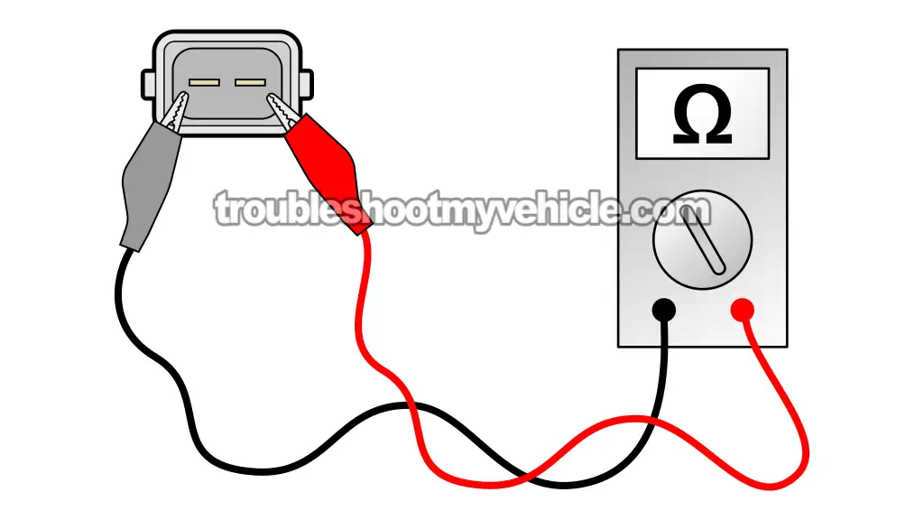
TEST 2: Hot Temperature Resistance Check

Now that you've finished the cold resistance check in TEST 1, it's time to heat things up and see if the sensor responds the way it should.
Once the sensor hits around 200°F, its resistance should drop into the 400 to 1,500 Ohms range. We're gonna get it that hot by dipping the metal tip into boiling water —since water boils at 212°F, that's perfect for this test.
If the resistance doesn't drop into that range while it's sitting in the hot water, the sensor's no good.
CAUTION: Boiling water can burn you bad, so take some basic safety steps:
- Don't touch the sensor while it's hot —let it cool before handling.
- Only submerge the metal probe of the sensor. Keep the plastic part and terminals out of the water.
- Use long jumper wires with insulated alligator clips to avoid getting near the heat. Need a set? Try these: Jumper Wires With Insulated Alligator Clips (at: amazon.com).
- This is an off-vehicle test —don't try it with the sensor still installed.
- Let the sensor cool down completely before putting it back on the throttle body.
Here's how to run the hot resistance test:
- 1
Connect the multimeter leads to the sensor's two pins.
IMPORTANT: Use jumper wires with alligator clips to stay clear of the heat. Don't get your hands near the boiling water. - 2
Set your multimeter to measure Ohms (Ω).
- 3
Bring a small pot of water to a boil on a stove or hot plate.
Got a kitchen thermometer? Check the temp —you want it around 200–212°F (93–100°C). - 4
Dip only the metal tip of the sensor into the boiling water.
CAUTION: Keep the plastic part and terminals dry —don't let them touch the water.
IMPORTANT: Use tongs or suspend it with a piece of wire. Never hold it with your hands. - 5
Watch the reading on the multimeter.
With the sensor heated up, the resistance should drop into the 400–1500 Ohms range. - 6
Remove the sensor and let it cool all the way down before touching it or reinstalling it.
Now, let's go over what the results mean:
CASE 1: Reading is 0 Ohms. That tells you the sensor is shorted internally. It's cooked —replace it.
CASE 2: Display shows OL (infinite resistance). That means there's an internal break —sensor's dead.
CASE 3: Reading doesn't fall within spec. That's another sign the sensor isn't working right. Time for a new one.
CASE 4: Resistance drops into the correct range. That's what you want —the sensor passed.
If this hot test checks out and it passed TEST 1, then the sensor itself is fine. If you're still seeing that code pop up, the real issue's probably in the wiring between the sensor's 2-wire connector and the fuel injection computer.
More 3.9L V6 Dodge Ram Van Tutorials
You can find a complete list of tutorials for the 3.9L V6 Dodge Ram Van in this index:
Here's a sample of the tutorials you'll find in the index:
- How To Test The MAP Sensor (1989-1990 3.9L V6 Dodge Ram Van).
- How To Test The MAP Sensor (1991 3.9L V6 Dodge Ram Van).
- How To Test The Fuel Pump (1989-1991 3.9L V6 Dodge Ram Van).
- How To Test For A Blown Head Gasket (1989-2003 3.9L V6 Dodge Ram Van).

If this info saved the day, buy me a beer!

